Hey Guys,
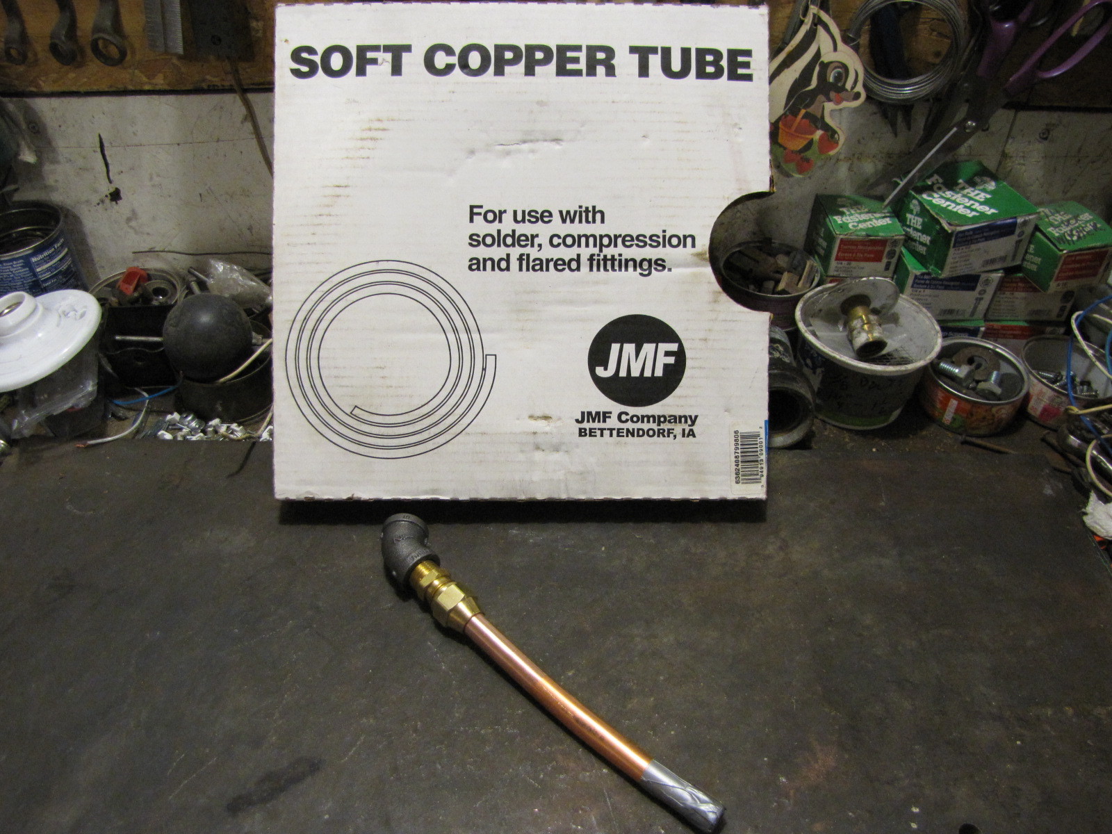
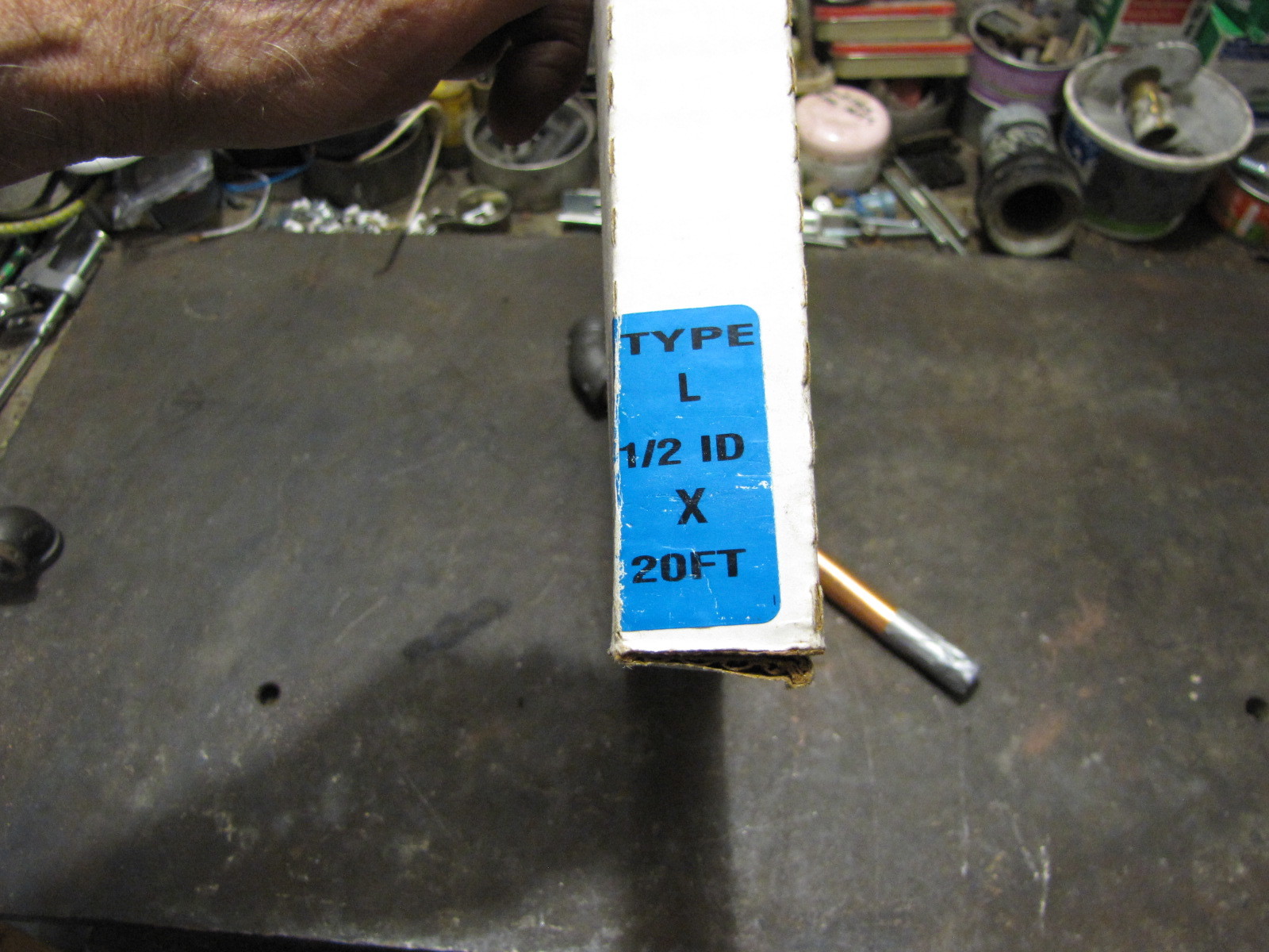
Thanks for the “annealing” tip. I found a good vid to illustrate the whys and how to. Here’s the copper I used and a pic of a jig to orient the 45* els on the tube for welding. I also watched a vid of freezing water in 3/8 tubing. Worked, too.
…two annealed and ready for the final bends. This is the tricky part. They’re annealed, so I’ll take them off, fill with sand, seal the ends with tape, attach the top connection and pray. It’s tedious, but it can be done. That’ll be tomorrow’s project.
If you notice my inlets are directly over the nozzle ports. GEK has the nozzle ports half way between the inlets. On my next build I will do the GEK configuration and hopefully be able to use a J configuration using 1/2" pipe and fittings. A small union will be needed for this for ease of assembly/disassembly.
Pepe
Looks good Pepe.
I’ve asked this question but not sure if it was answered. Does the frequent heating and cooling of copper make it brittle? If not, it sure would make a good air intake preheat.
Bill,
I don’t think so given the annealing process info I’ve read.
Tom C,
I like that. I wanted to do something like that. I had the copper so I used it. It was a real pita to work with the copper as it goes out of round so easily. After one try I had to put the flare fitting on first before bending the pipe otherwise it was a fight to get it on the pipe.
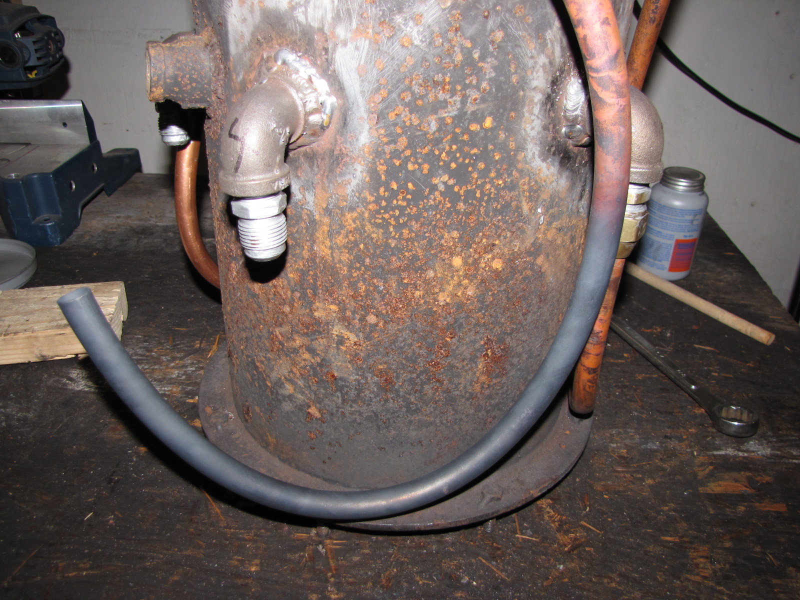
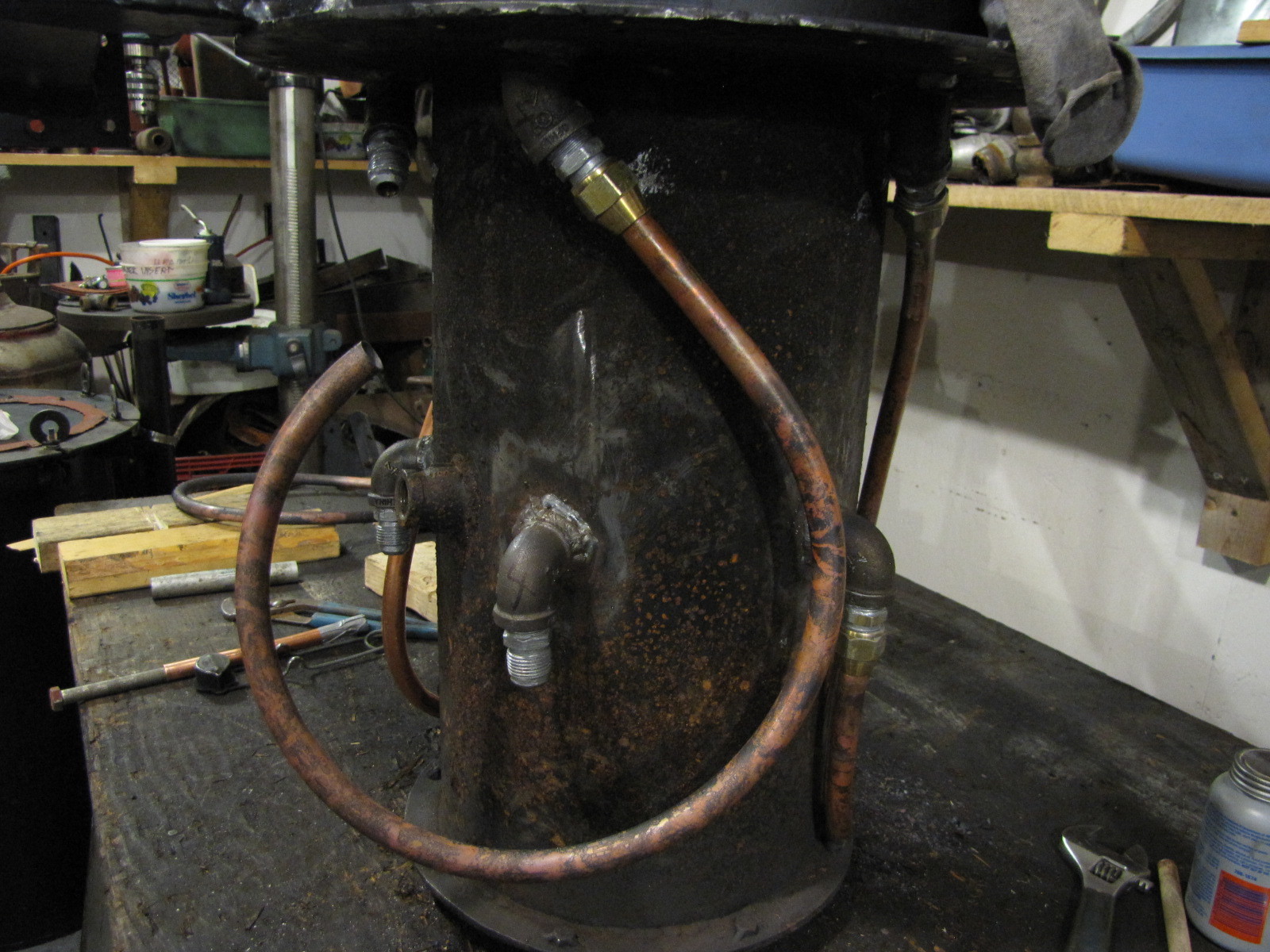
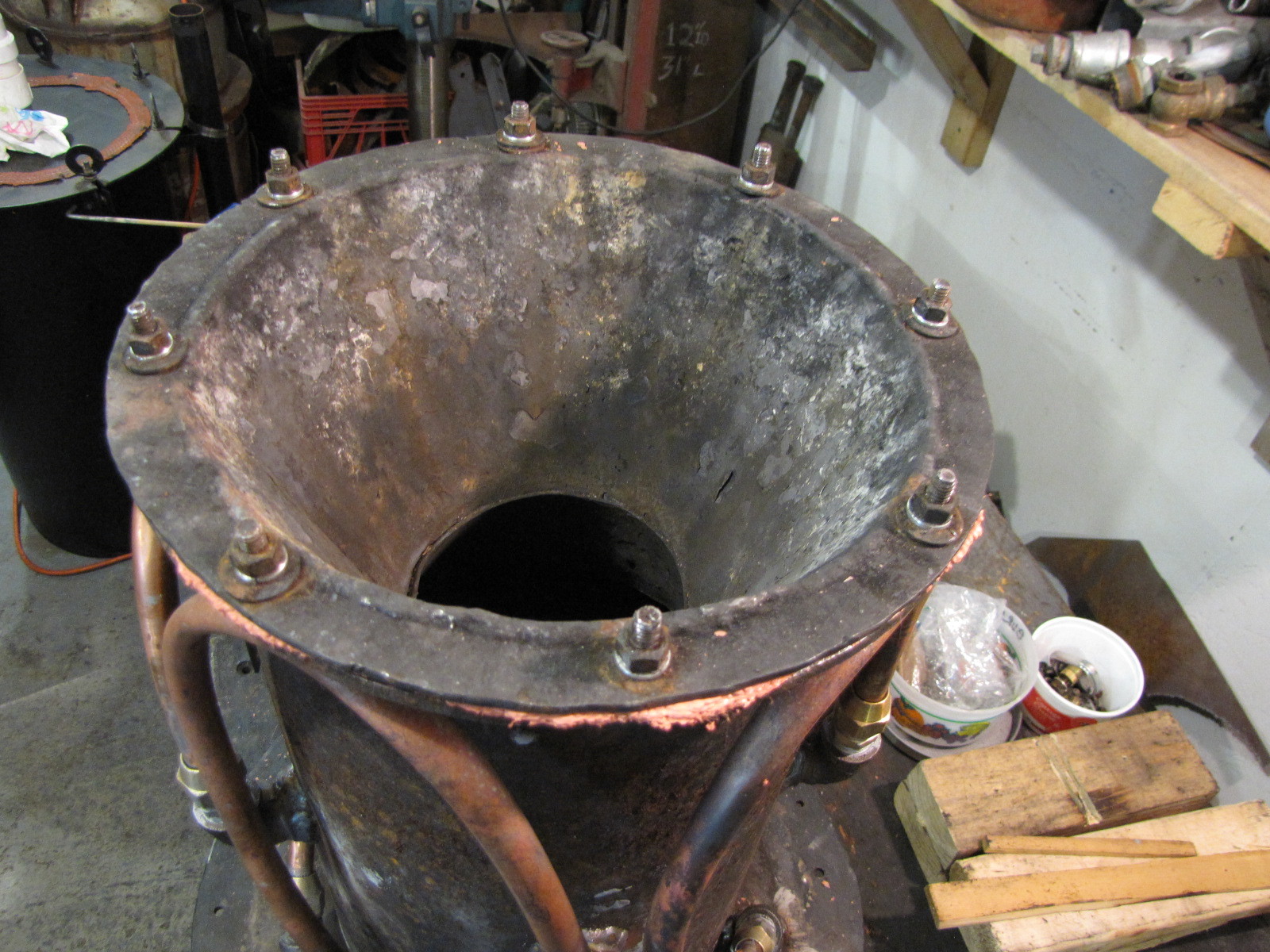
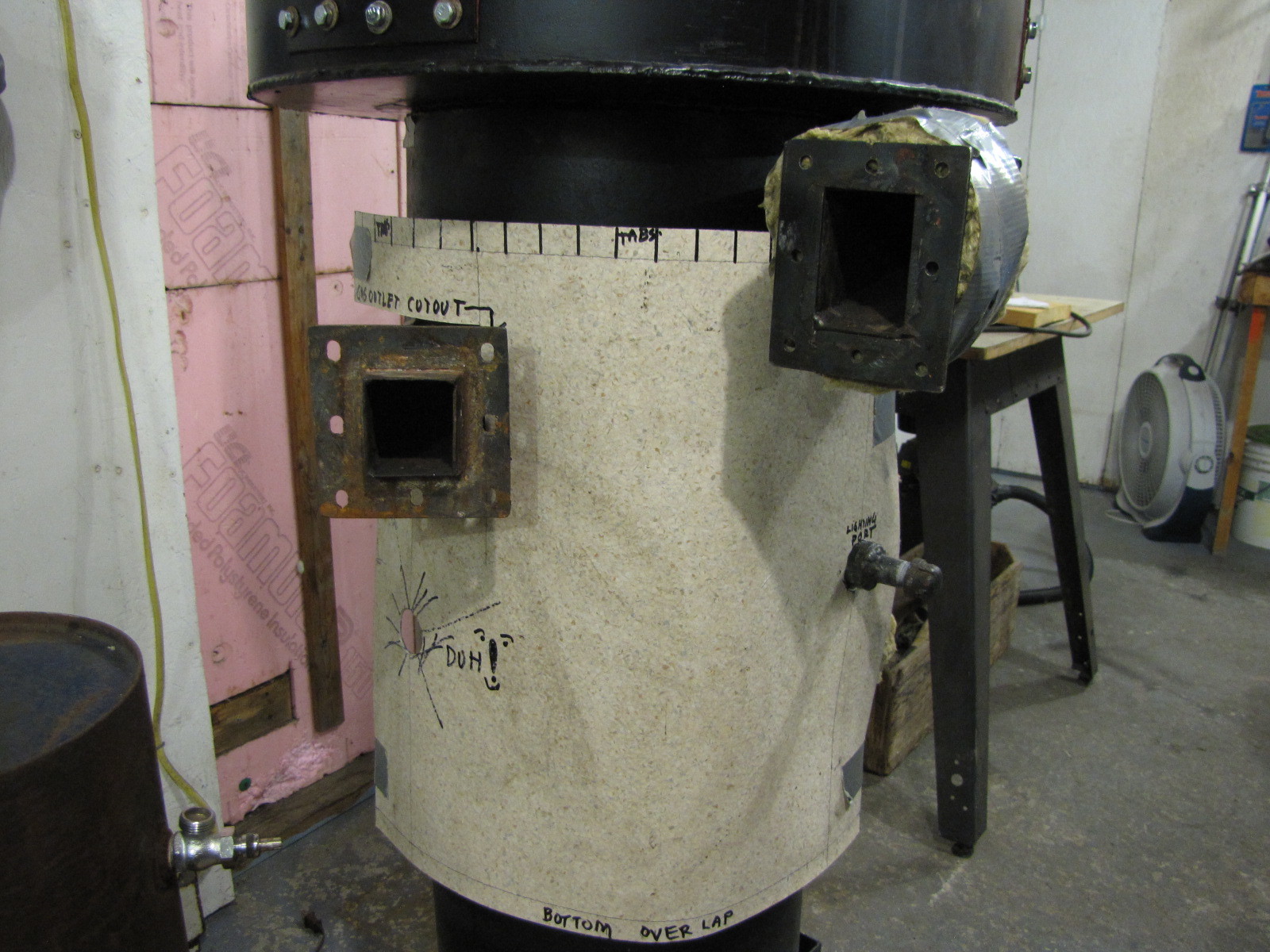
There, I finally have all 5 copper air inlet tubes installed. You can only see 4 here, but trust me the fifth one is done. Man, that was trying for sure. With a little design shifting, I will be able to use 1/2" pipe and fittings with a union to make the final connection on my next build. No more annealing! I’m ready to drop this baby into the burner shell.
The unfilled port is the lighting port. I will also be able to stick a thermocouple in here to read the temperature at the nozzle level. I wanted to be at the restriction level, but it wasn’t a quick fix thing. I will design it into my next build.
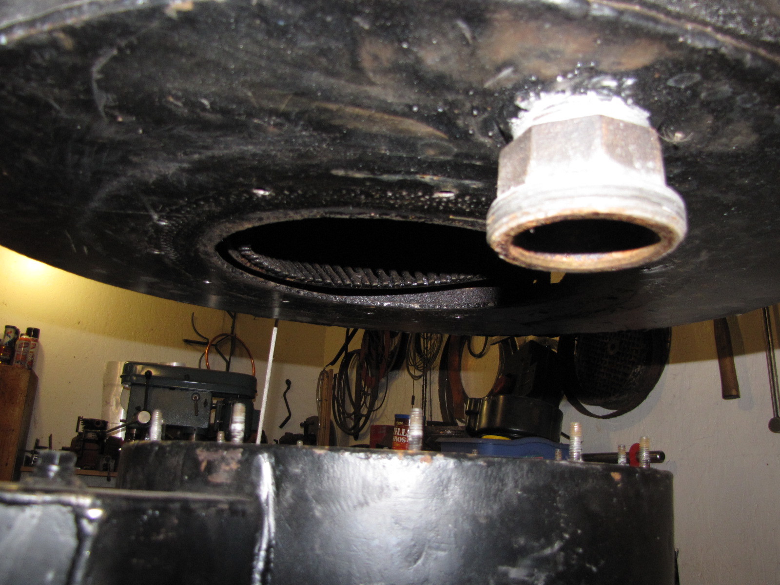
I put a new gasket on the hourglass hearth and bolted it in place. I used fiberglass flat gasket impregnated with Flame Buster caulk. I’m impressed with the performance of this combination in this application. Note that I always use new lock washers on a reinstall.
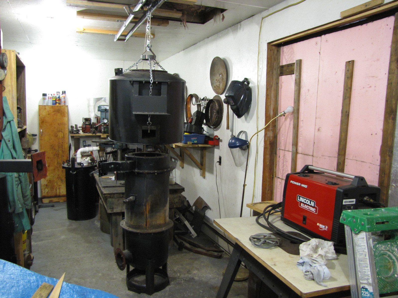
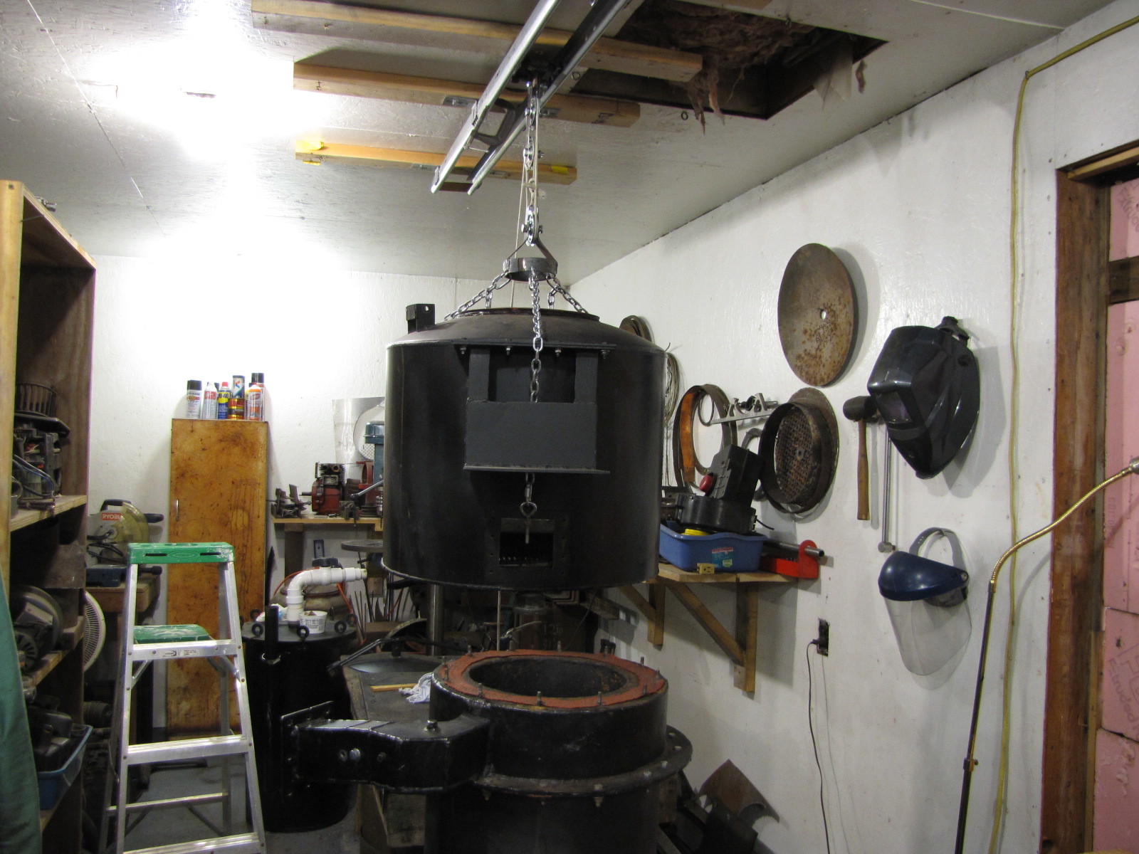
I’ll do a dry run to insure a good mating of bolt studs to hopper mounting holes. I don’t want to be messing around once I get the Flame Buster on the gasket. There’s not a lot of play time before it starts to set up. I try to get it in quick and bolted down.
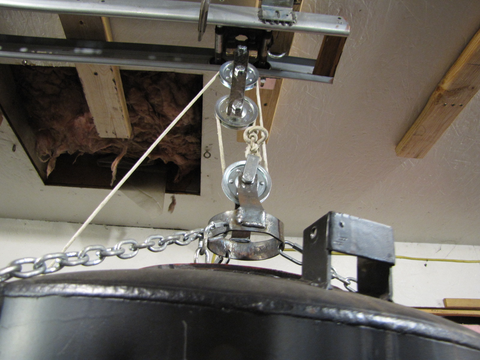
Then I’ll roll the hopper back out of the way, work on the gasket, roll the hopper back and set it back on the studs. The nuts are installed from inside the hopper. After moving the grate out of the way, the nuts can be installed through the 3 inspection ports. Then they are tightened through the top with a small impact driver. This fastening arrangement needs a change, it’s a bit cumbersome, but doable. It’ll give me something to play with on paper. The trolley needs to be long enough for me to pull straight down the outside of the hopper through another pulley mounted at that end of the trolley. Presently, it moves in the direction I’m pulling from. That’s the reason for the clamp on the rail. A bit cumbersome. Another mod.
Mechanical advantage 3.
Brian,
The posts for the trolley build are in my comments, #'s 302,307,312. Remember my comment above about making the trolley longer to direct the pull straight down instead of angled which is a pitn (neck) to deal with alone. The new trolley will be about 18" long with dual wheels at each end. The new dolly will have another pulley which will direct the force straight down instead of the present sideways force which pulls the unite sideways instead of just lifting it straight up. There is also a large eye screw screwed into my bench top to tie off the rope once the trolley is in place.
Pepe
Hey All,
On and off showers today, so I spent some time on energy conservation items. Felt good to be in the shop, unhurried. Had good concentration for the fitting process.
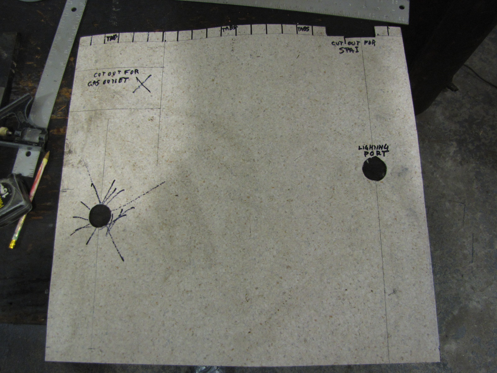
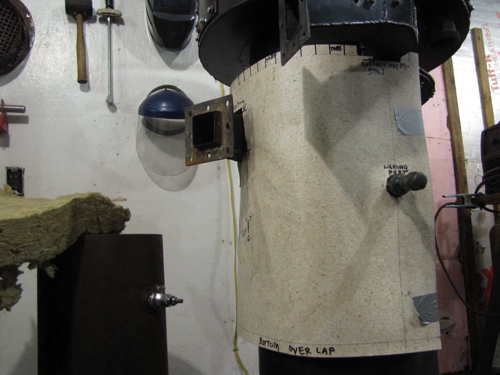
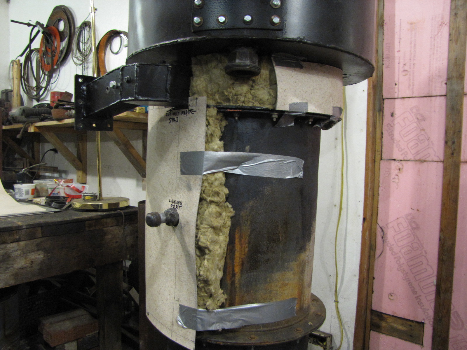
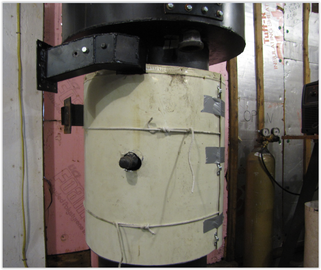
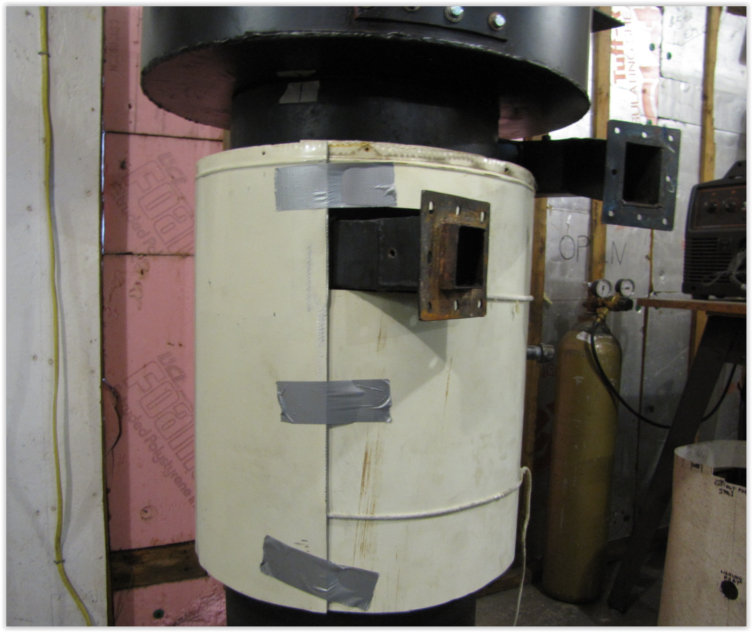
Fitted pretty well and duct taped in place. The lines at the top will be tabs. Every other one will be bent down onto the flange to sort of hang the cover in place for installation. The other tabs will be used to secure the SPAI manifold cover to the burner shell cover.
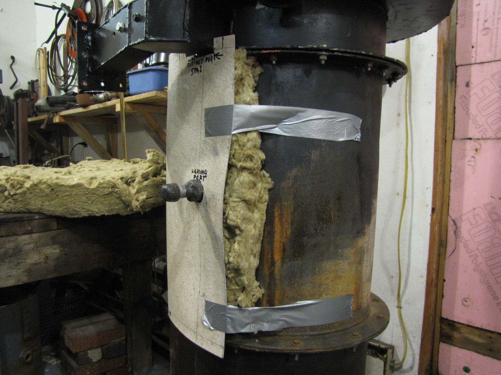
Install 1 1/2" rock wool (flush with edge of flanges). The space below the lower flanges is below the bottom of the grate. and occupied by the reduction products (CO, H2, etc). This is the finished gas and can begin to be cooled now.
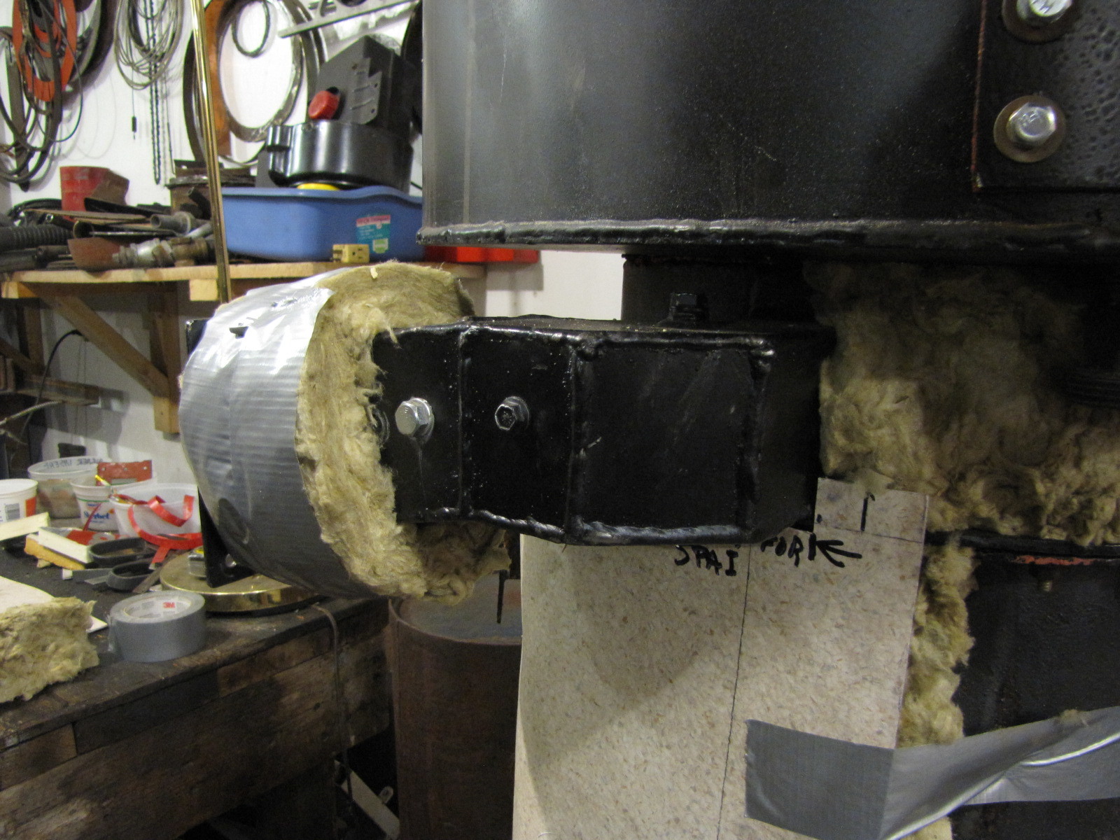
Wrap SPAI preheated air delivery tubes with an inch or so of rock wool wrapped in 3M duct tape, the best, imho. Over lap tape to keep this water tight.
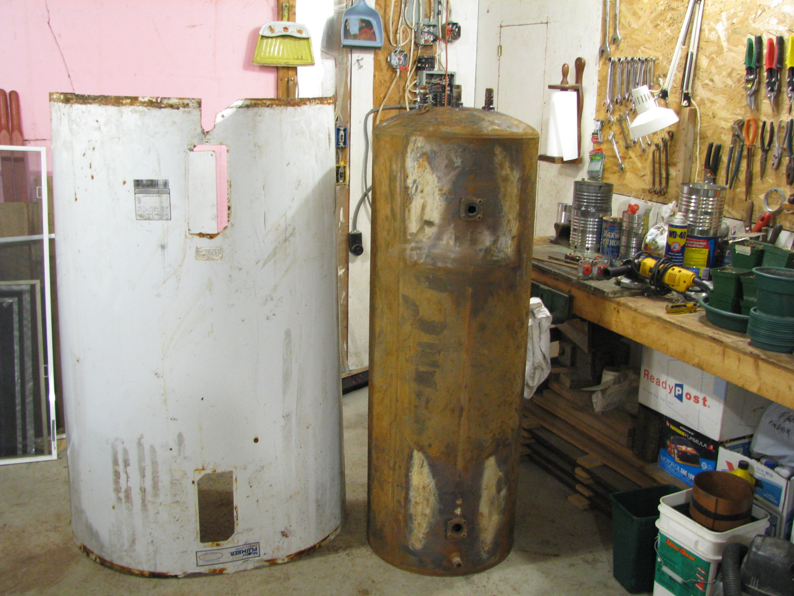
I will cut the coverings out of an old HWH shell. It’s already painted and pre-rolled more or less for ease of use. You do save yours, right?
To my fellow Veterans and all Americans, thank you and God bless America.
Pepe
You do remember that it’s “Memorial Day” and not “Veteran’s Day”, right? Today is for remembering those who are lost in service. One of my vet friends pointed out to me that thanking a living vet today is almost a sarcastic death threat.
Hey Everyone,
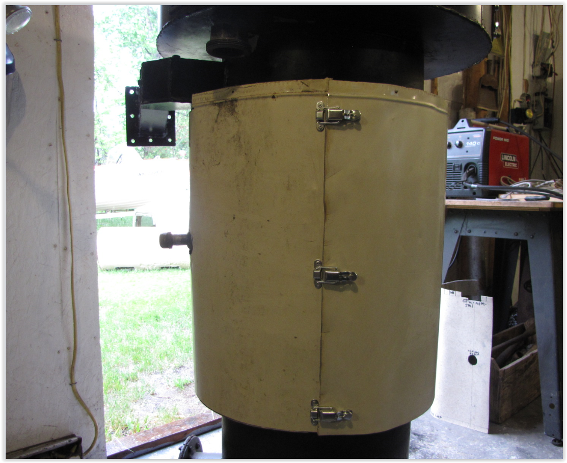
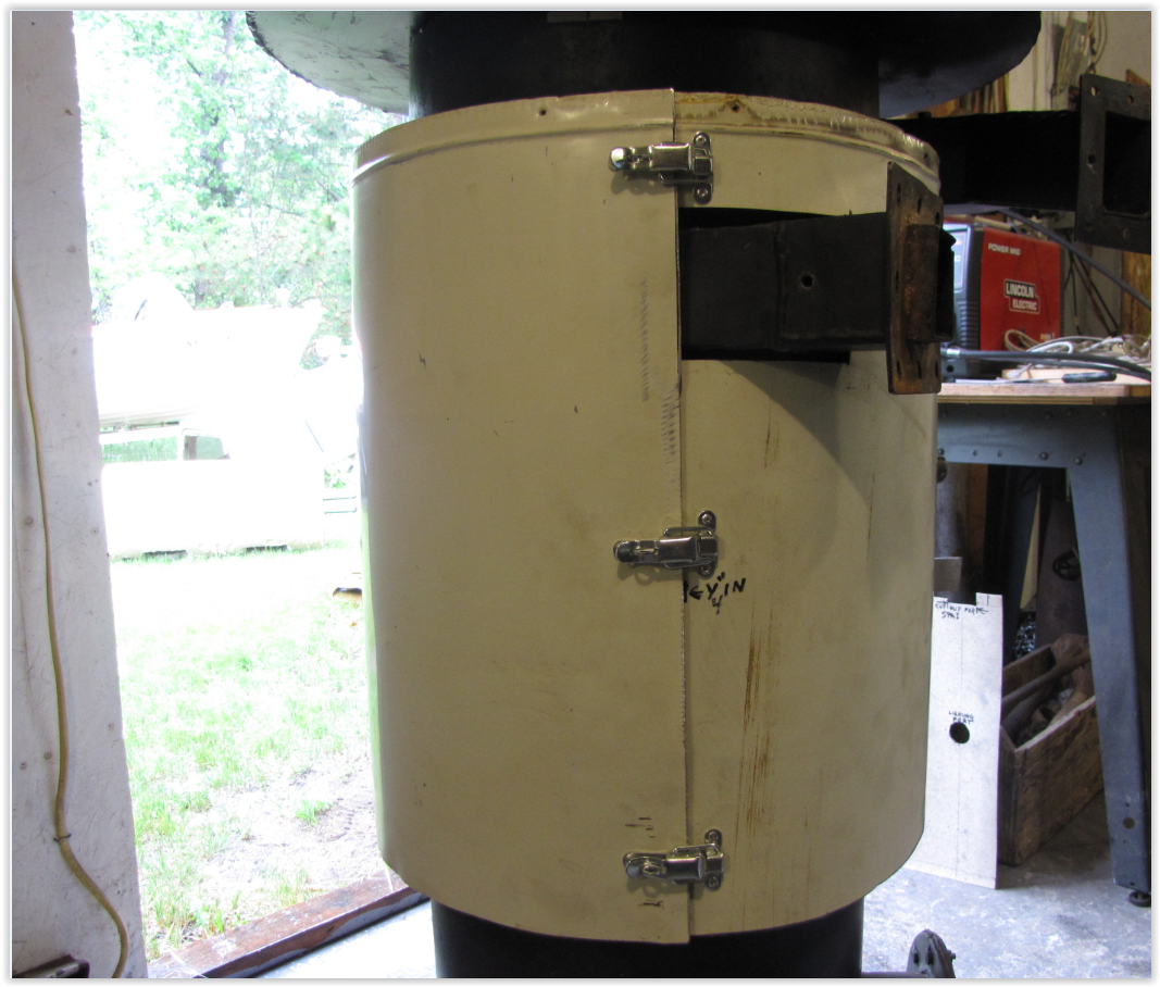
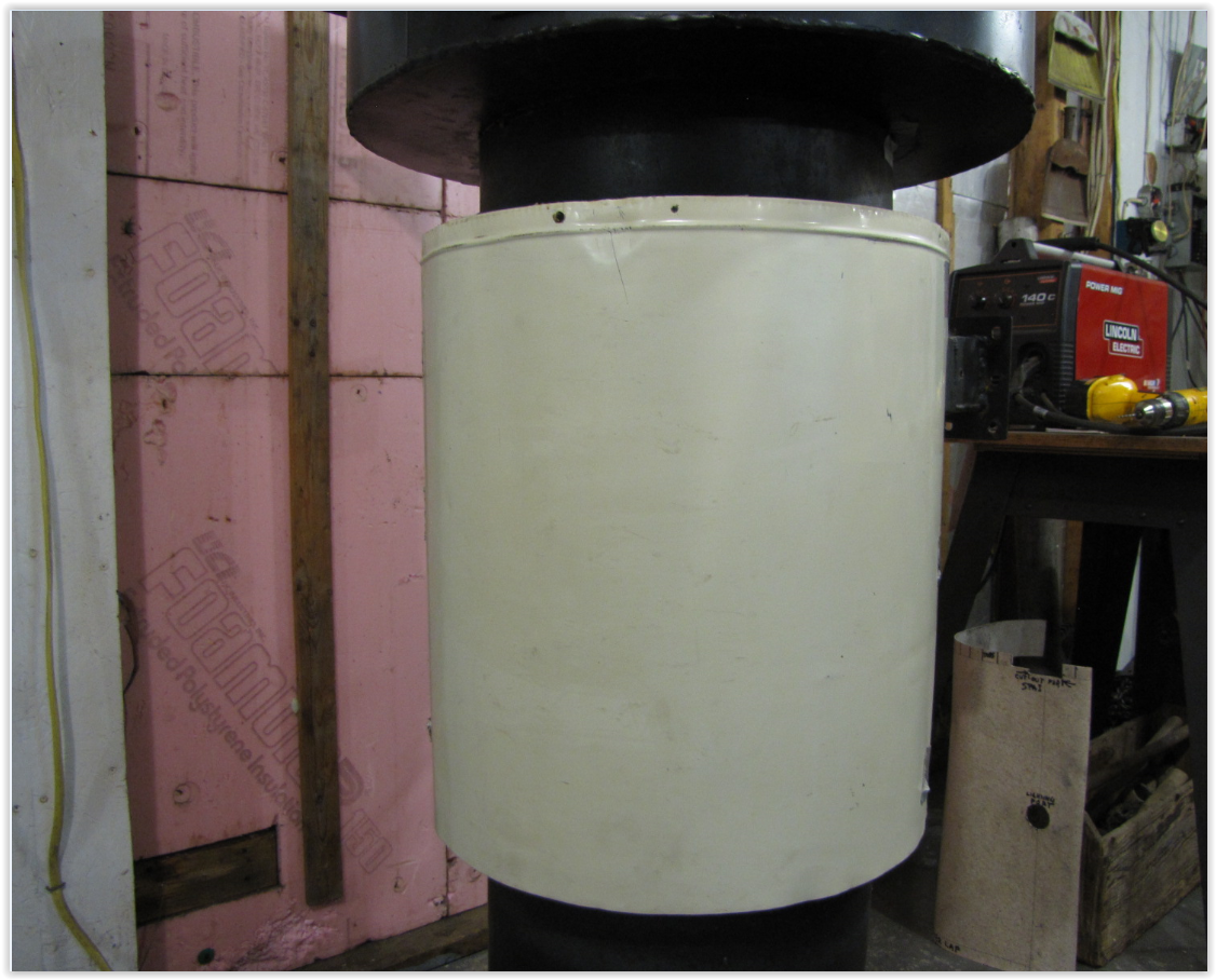
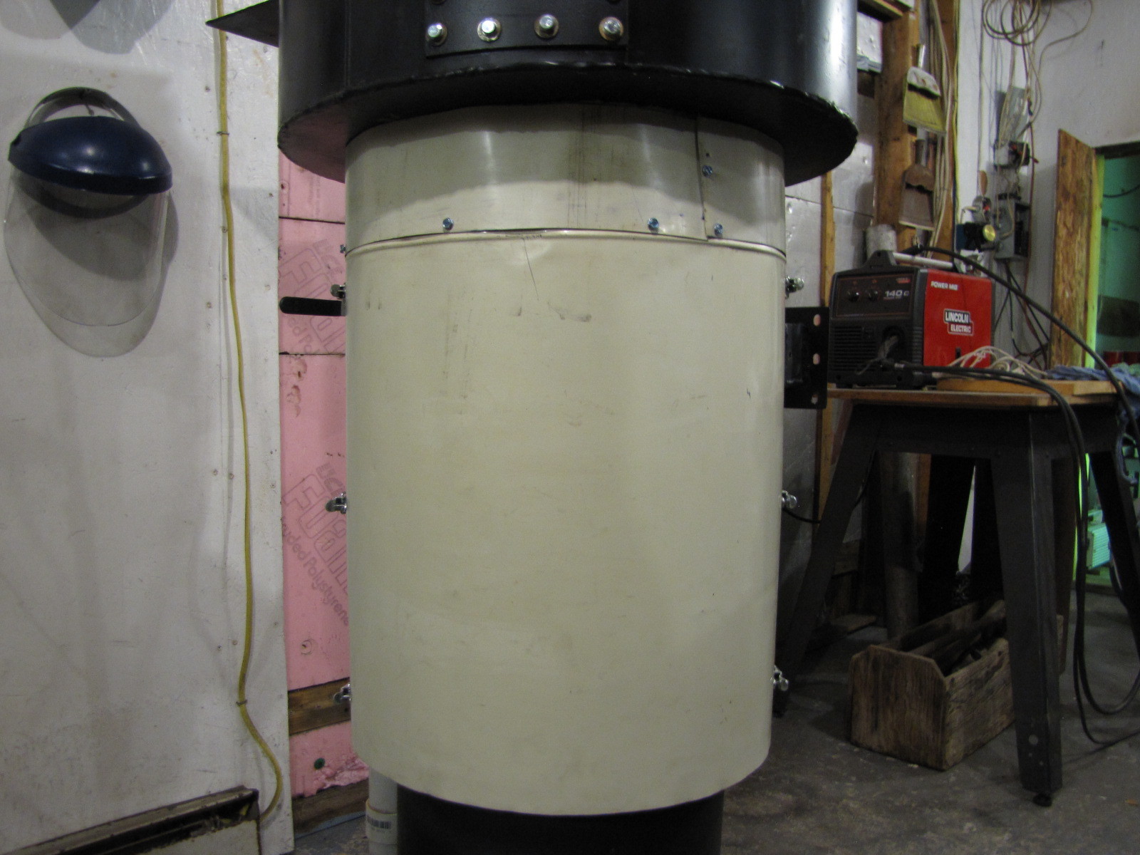
I put the pattern to the metal, cut it out and roped and taped it in place with help from my right hand woman, my wife. Then I installed the snap closures and sat back and smiled at the results. I’ll install a narrow strip on the top of this up to the bottom of the hopper (also insulated).
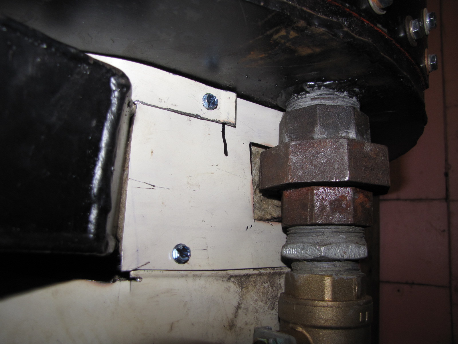
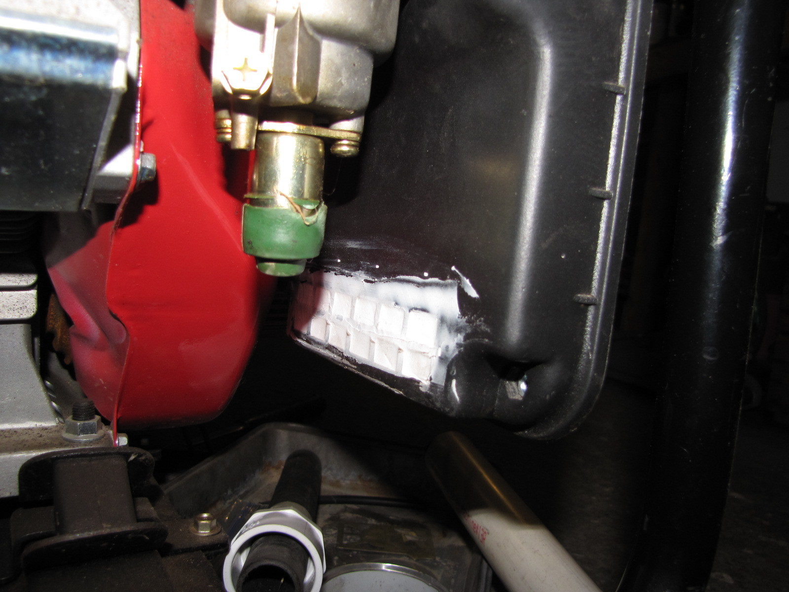
Yup, the union is too close to the body. The good news is that I can move the drain hole out an inch on my next teardown. The other good news is I can just leave it as is.
This is 2" d heavy tubing that I can garner 4 identical 90 degree sweep els from plus assorted pieces of 2" stock. Priced $10 at a garage sale this am, but she took $5. Wish I could find a dozen of these. Check out the heavy duty receiver for the rail, which has a casting to fit. Talk about tough, it has to be an oldie. They don’t make them like that anymore.
A gift, I’m saving for ??? Here’s what I mean, it’s 1 1/2" x 1 3/4" and light weight. I’m ready to move the unit outside now and reassemble it. Then I can finish some minor insulating of the hot air delivery tube from the cyclone to the SPAI manifold inlet.
Pepe
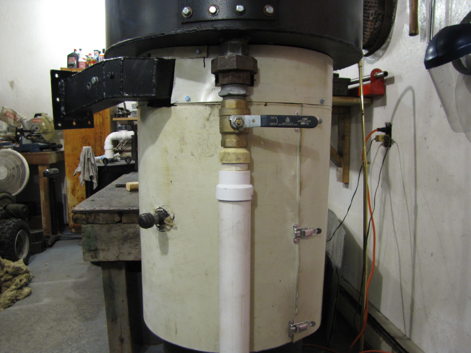
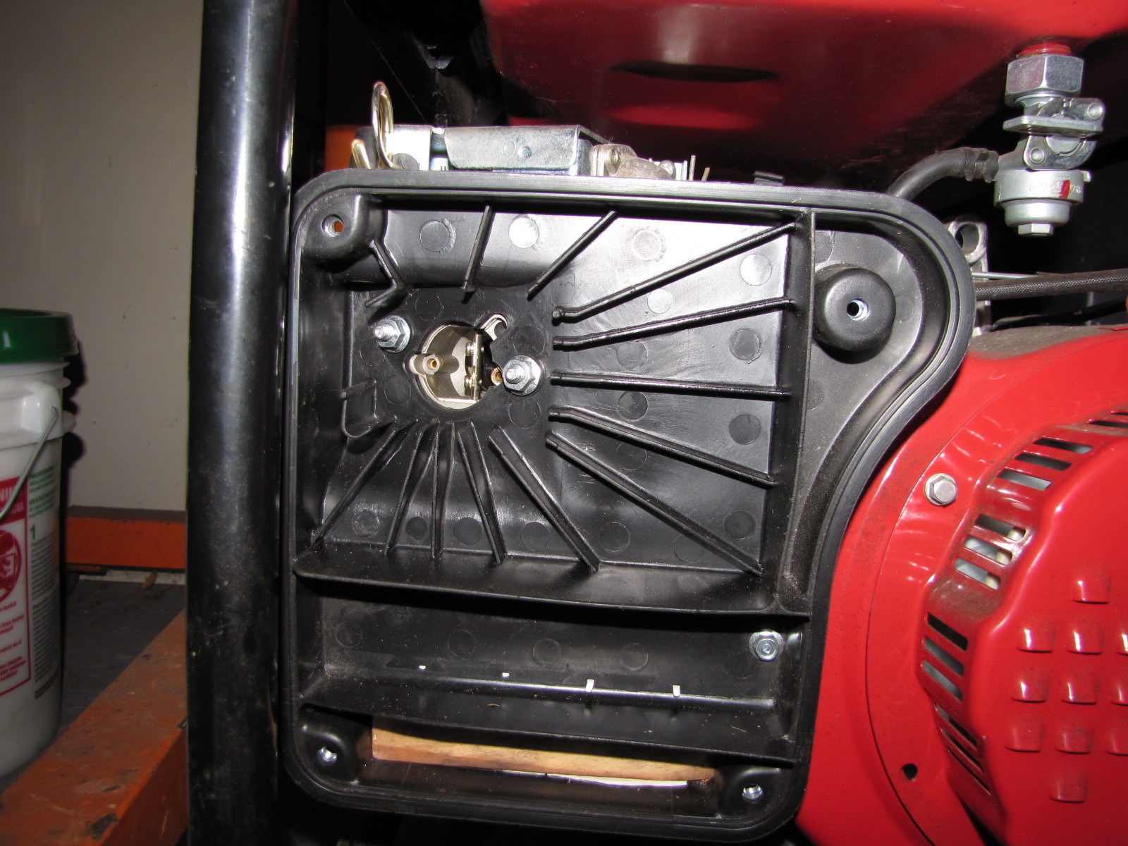
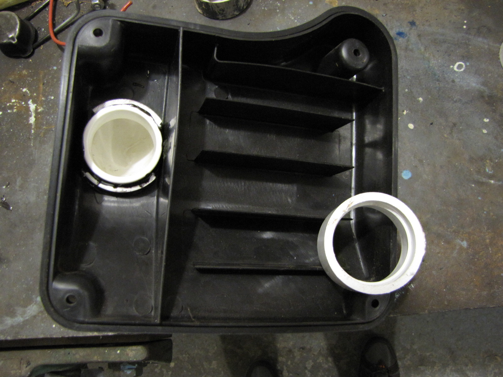
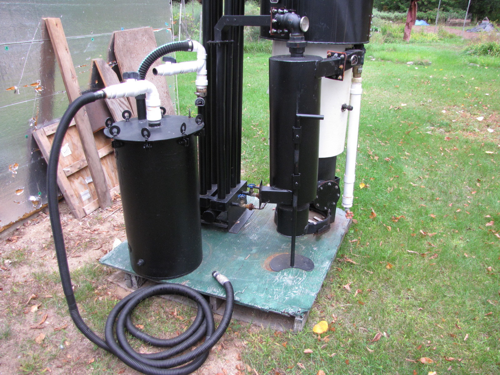
This is the mock up. Need to add drain cap on drain catchment ( if you have water here, you have a bigger problem elsewhere) and a 4 hole bracket to secure intake pipe. Woodgas is delivered through 1 1/4" drain hose via a tapered vacuum cleaner tube friction fitted into the intake pipe.
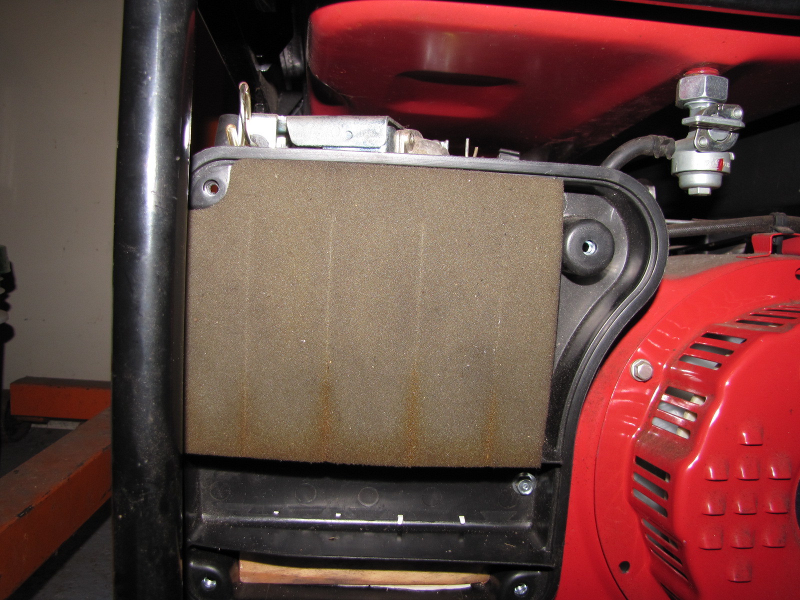
Note to self, can’t leave the choke lever unattached, not sure if it will flap in the breeze(so to speak) and close or flutter during operation.
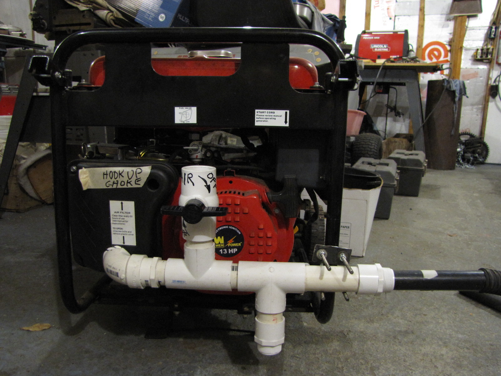
Hose is shown in filter/run port. Note other port and shutoff used for start up and flaring that keeps low temp tars, etc. out of filter medium. Close one valve open the other and switch the friction fit tapered end piece to the run mode through the filter. It’s quick and easy and air tight.
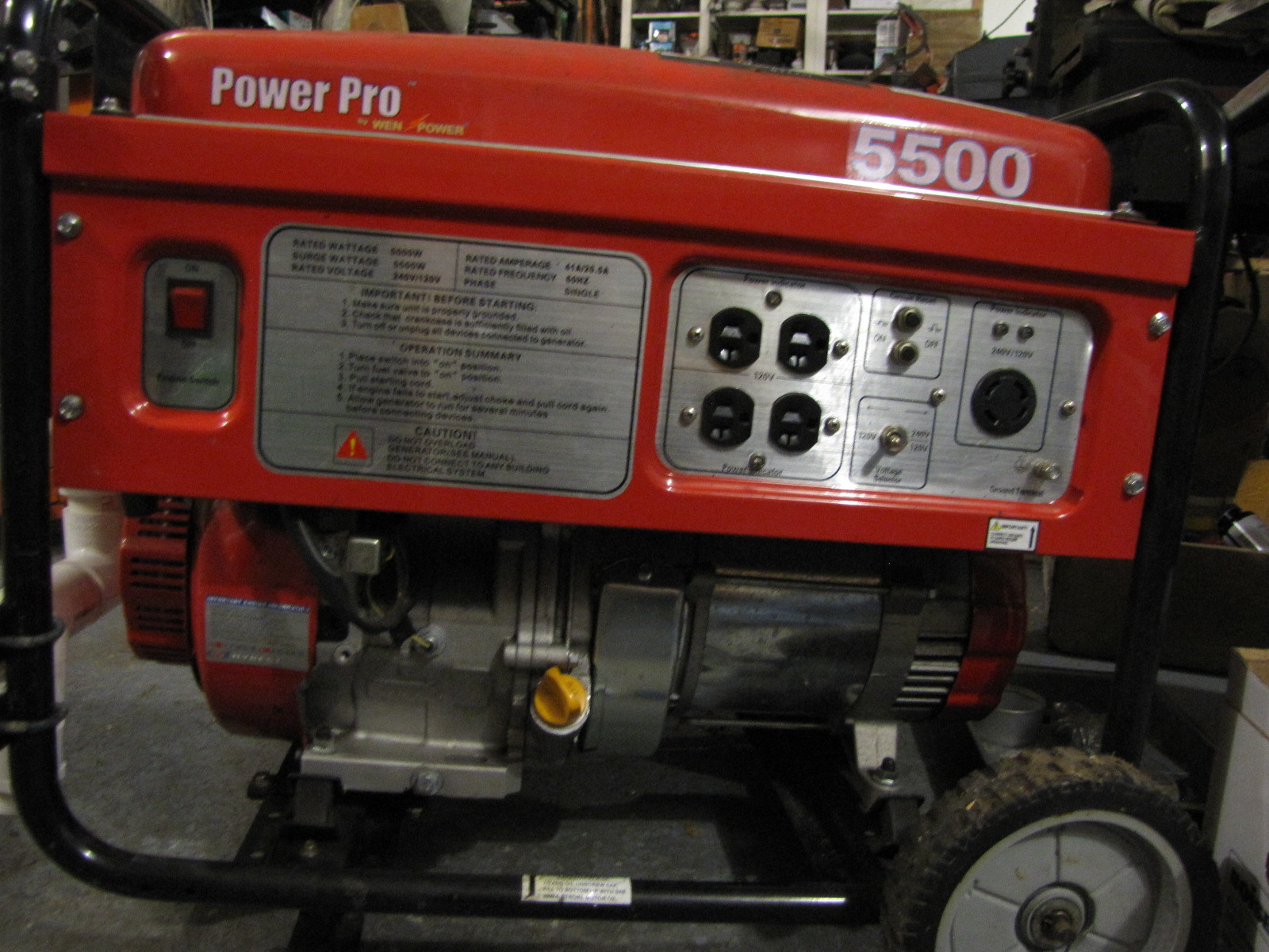
Now, I’ll be able to “load” test the unit and see how it performs “doing some work”. Hopefully, early this week. My wife picked this up at an auction last year for $275. Probably saved 50 or 75 bucks. Runs great on gasoline,we’ll see how it does on woodgas.
Pepe
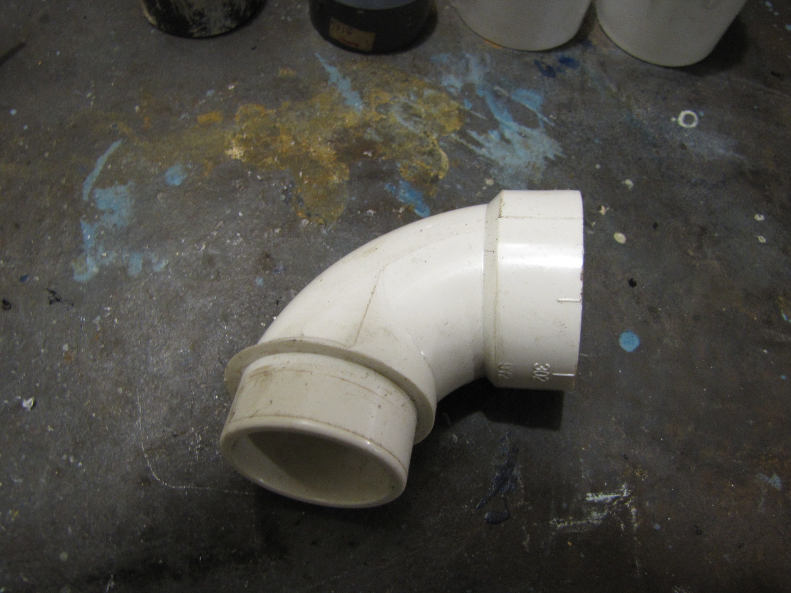
You’re right, Arvid, they do suck, but I had this hanging out and decided to use it anyway. I tried a silicone spray but the valve stayed hard to operate. None of this is glued up yet, so I may break out all my assorted boxes and search for an old gate valve.
Pepe, I don’t glue any of my plastic fittings. They fit tight and sometimes I put a wrap of duct tape at the joints. But I am always able to take things apart without buying new connectors. TomC
I tried plastic once… on the john deere m tractor I built… they got traded out for brass 1/4 turn valves pretty quick. I’ve stuck with brass 1/4 turn ever since.