Speaking of monorator hoppers, check out this article.
http://mars.ymex.com/~s-20222/gengas/monorator-eng.html
Figure 5 monorator design will replace my drawn diagram, much less welding, much less cutting and easier welding for the internal condensate “fence”. This design supposedly will handle wet fuels. Fits my purpose to lower my unit height.
Arvid, I like your lid and handle design, nice. I’ll be doing something similar for the 24" diam monorator hopper.
Good info, good read.
Pepe
1 Like
Hello Fellow Gasers,
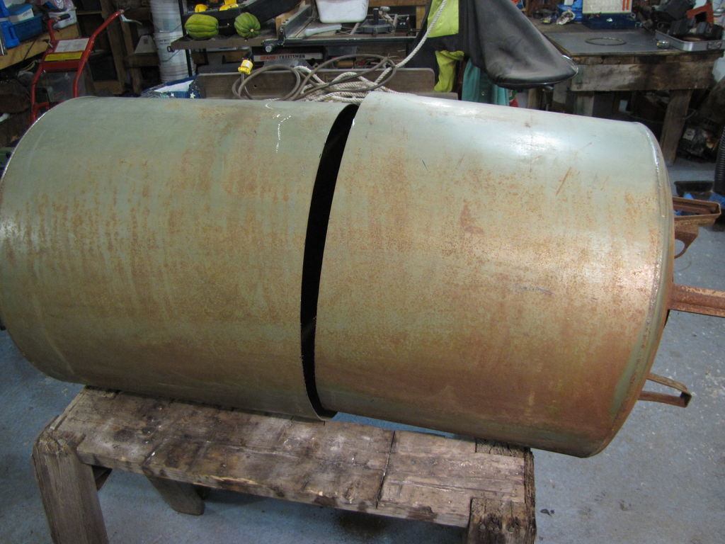
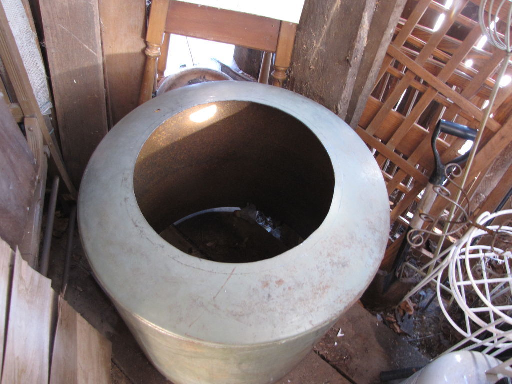
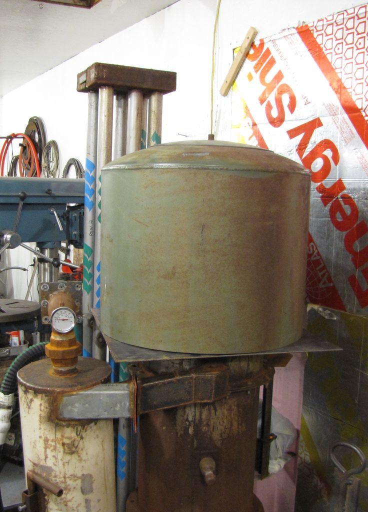
I finally got back to business and started my monorator hopper. The larger cutout (from the top of the tank) makes a great fitting cover. Now to cut out the monorator mounting plate base, line up and drill the mounting plate holes and weld in the gutter plate, Then comes the trick of rolling the hardware cloth (heavy metal screen) into a cone. This cone will be held in place with occasional spots of JB Weld. This will allow water to drip into the gutter and to funnel the fuel into the firetube.
The Dewalt jig saw has heavy metal cutting blades, I haven’t broken one yet and I’ve cut 1/8" plate , not fast, but steady and accurate. The tank is a hair under 7/64" thick.
Pepe
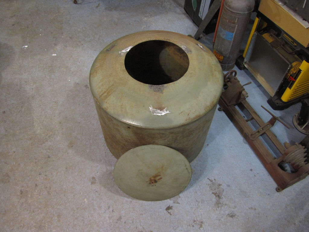
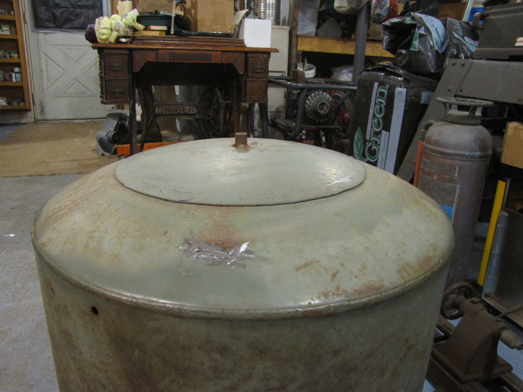
Edit: I went back out to the shop and stacked the pieces in place just for a look see. This monorator is 21 1/2" tall. This is 14" shorter than the old hopper. The volume is 4.71 cubic feet. The old volume was 3.58 cubic feet for a 1.13 cubic feet increase, about 31 %.

nice lid
Looking very nice Pepe
Thanks
Patrick
Thanks Arvid and Patrick for the comments. I’m hoping to get a 3 to 4 hour burn with the increased volume. My original figures were incorrect as I already had a 2 hr burn with the smaller hopper.
I have to get the 18 hp engine on track, nothing serious, just has sat for 1 1/2 yrs. If you recall I increased the hearth size on my unit, and as Dan Cox pointed out, my 8 hp engine might be under pulling for optimum performance. I agree.
Can’t wait for spring so I can set up outside again. We’ve been below zero for a couple weeks now.
Pepe
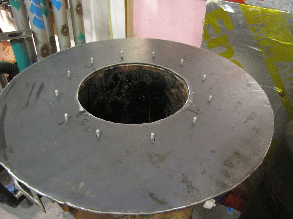
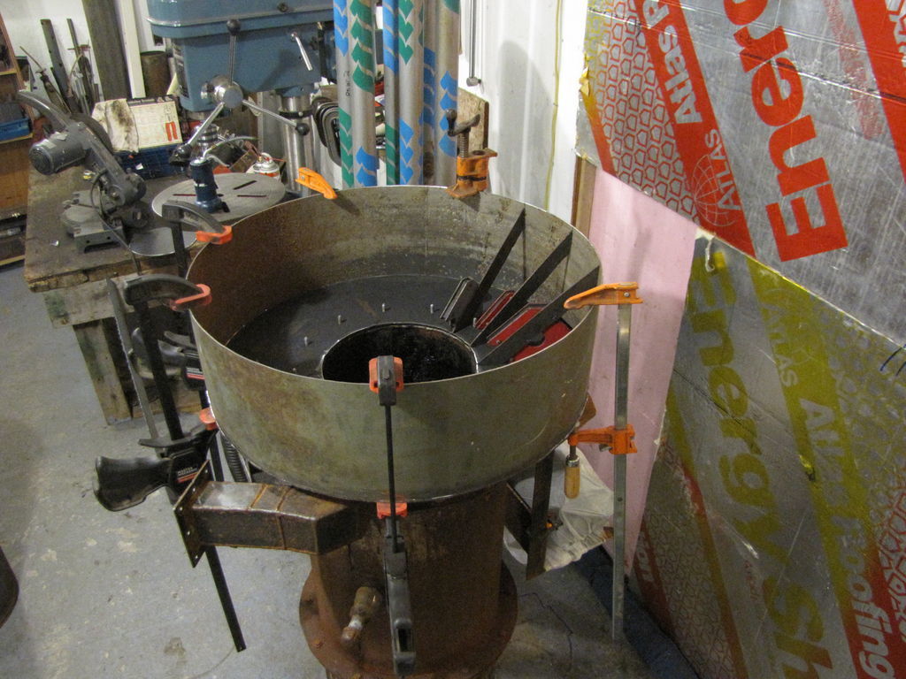
I got out early this am and tackled the base plate bolt pattern on the existing burner unit and transferred it to the base plate for marking and drilling.
Pic 1 Monorator base plate with 9 3/4" d firetube cutout.
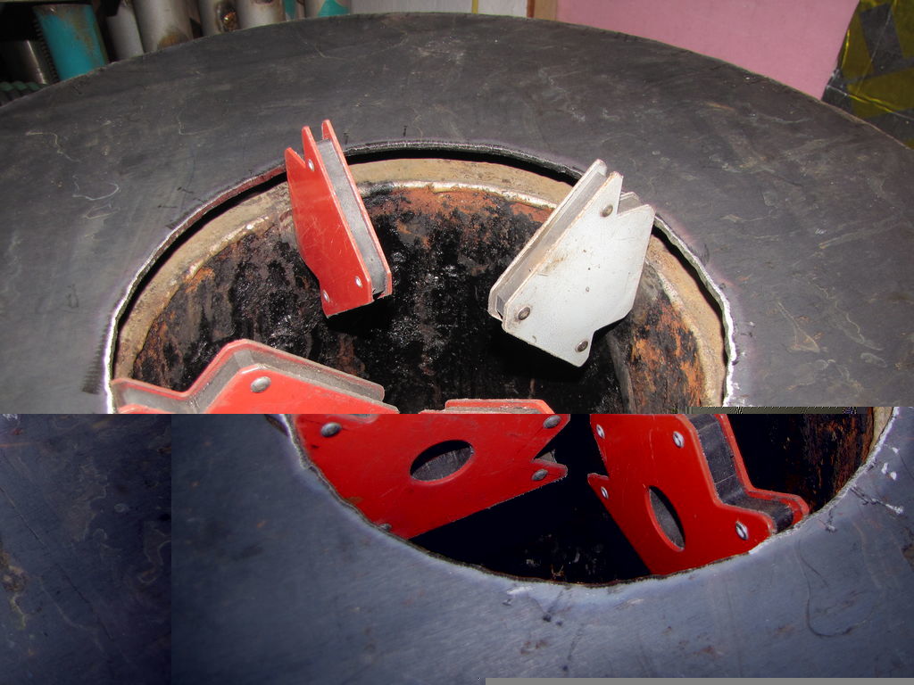
Pic 2 It’s best to have a hand with placement, etc with this large an item.I used magnets as a line up tool. Index the base to the burner shell and carry this index mark up through all the operations. If the base gets welded on upside down, it’s doubtful the lineup will go well.
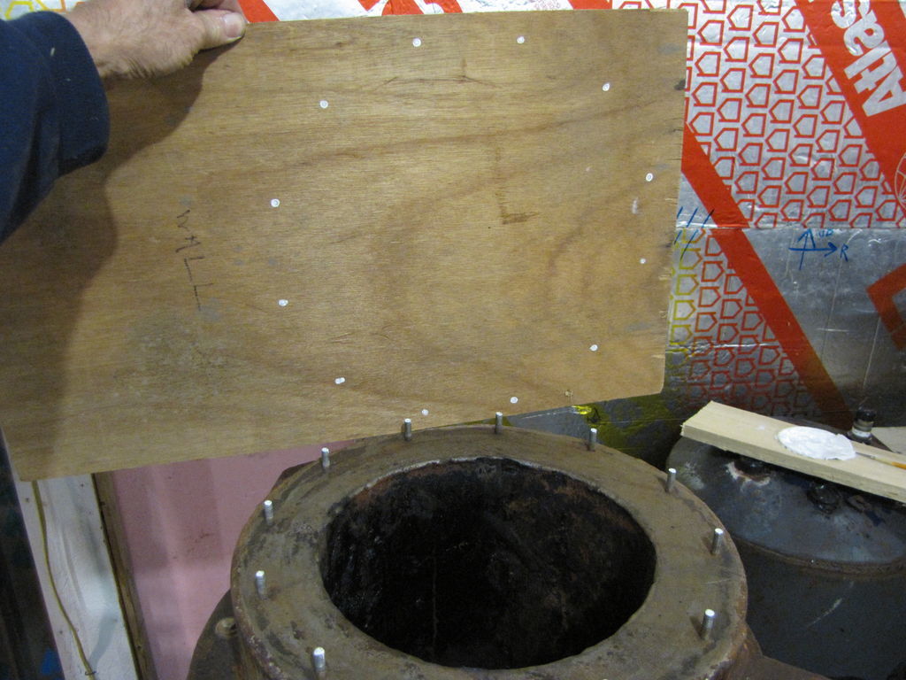
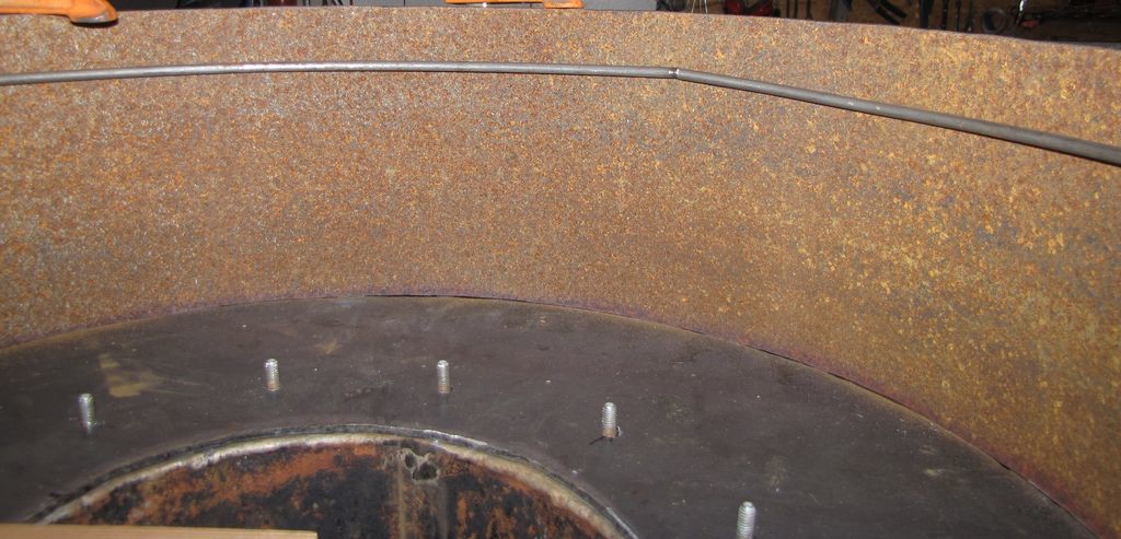
Pic 3 I put a dab of paint on the top of each stud and pressed my pattern board onto it to get the bolt pattern.
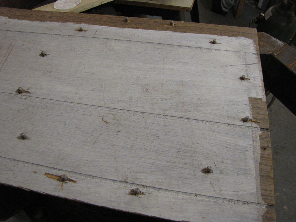
Pic 4 Carefully drill out the mounting holes, keep centered as much as possible. The pattern is in the installed position for the base plate. Envision placing the base plate on top of this so the holes are in the correct orientation. You will be marking and drilling up through the bottom of the base plate. Reread Pic 2.
Pic 5 I indexed the pattern to the base plate and started each of the holes to locate them. I removed the pattern and finished drilling the holes. I had to do some tweaking as you can see, but that’s life when you work alone. Won’t hurt the function at all.
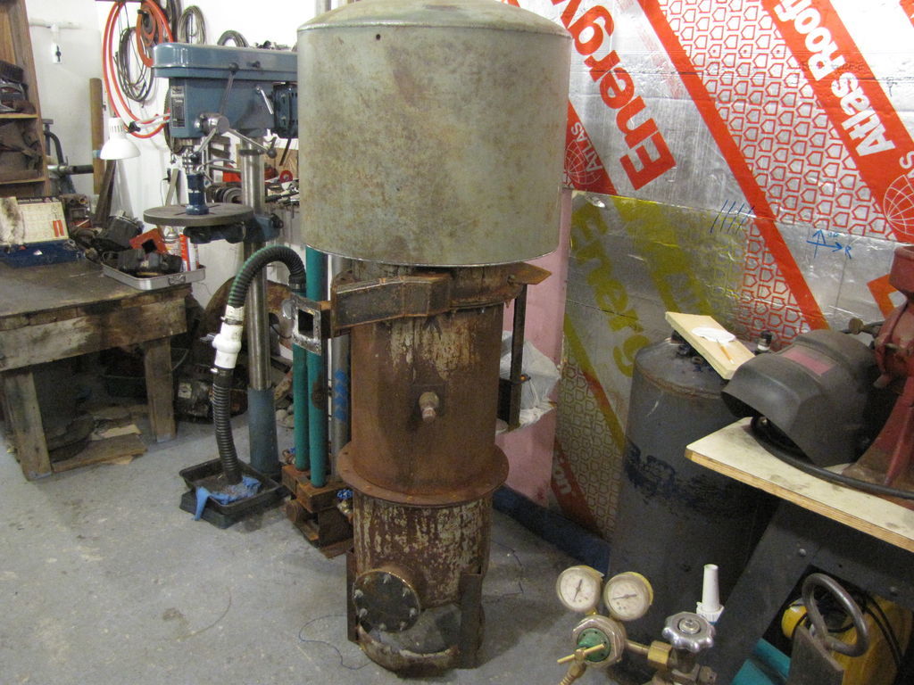
Pic 6 My unit is only 66 1/2" tall. I finally don’t nee an extension ladder to load the hopper. The volume on my last post doesn’t account for the volume for fuel lost under the sloped screen cone. I’ll recalculate and post that when I figure out the cone. I also need to relocate the thermometer on my SPAI. I’ll move it to the face.
The funny thing (for you guys) is that I made a pattern for the old hopper (same bolt pattern). Huh? Oh, I tossed it when I got done the old hopper.
Lesson, never toss anything on a beta.
Pepe

looking good, i’m a fan of loading from the ground level… or atleast the same level the gasser is on. I hate ladders
Hi Richard, if your engine is to only be used with the gasifier you could get longer runs too buy increasing the compression ratio to 17 to 1.
I am using a 200 litre drum as a hopper and get 6 to 8 hours run, but need to use a ladder to fill it.
Edit 2/8/14- I changed my design to something much easier to build. See below, 02-08-14 post
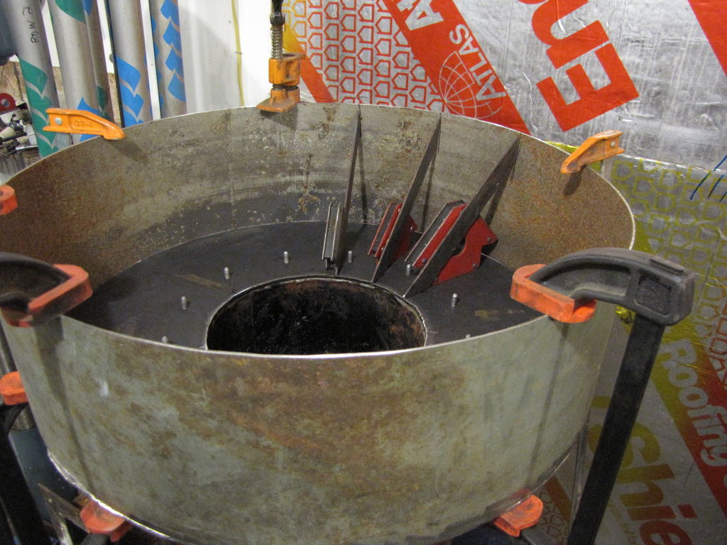
Well, I finally put a design together for funneling the fuel into the firetube. I cut an 8" section of leftover tank to facilitate designing without a top in the way. The “funnel” will be a series of 8 small cradles each covered with 1/2" x 1/2" hardware cloth or with a series of 3/16" rods spaced 1/2" apart and welded to the cross braces. I’m thinking the rods will let the fuel slide with less resistance. I haven’t found a cheap source of rods yet. The cradles can be installed through the fuel lid and will be held from slipping forward by a notch resting over a weld bead. They will just be placed side by side with the last cradle filling in the last spot. This will allow me to bolt the monorator hopper down first with out needing holes in the cradles. Easy in, easy out. The condensate gutter will be installed behind the mounting studs completely out of the way. Love those magnets for layout. I can’t wait to try this baby out!
Pepe

As promised I recalculated the volume increase with triangular portion removed.
EDIT triangle is 7" not 5". Numbers are correct now.
Ok, now that I have some real numbers for the triangle ( 7" high x 7" deep), I can recalculate the hopper volume increase.
- Let’s start with the volume of a 24" circle 7" tall ( the height of the triangle and also its length since it is a 45 x 45 degree triangle). This is pi x r squared times the height or pi x 12 squared times 7 or 3166 cubic inches. Next find the volume occupied by the 7" high section of the fire tube with a 9 3/4" diam. Pi times 4.875 (radius of firetube) squared times 7 or 523 cubic inches. The difference is the volume of the outer circular section or 2643 cubic inches. Since this is a 45 degree triangle we are only concerned with half this volume or 1322 cubic inches. Dividing 1322 cubic inches by 1728 cubic inches per cubic foot that volume is .76 cubic feet. Subtract this from 4.71 cubic ft gives a usable volume of 3.95 cubic ft. The original volume of the old hopper is 3.58 cubic ft for an increase of 10.3 % fuel space. That’s an ok number, since I was mainly interested in a lower profile.
Pepe
Thank goodness I didn’t have to resort to the long forgotten differential equation solution.
Hi Pepe;
I can’t wait to see how it works also. I’m not sure if you can get 3/16" welding rods (gas) but you could check with welding supply store and see. You could buy these in bunches. I used s.s. rods in my bag house filter but they can get costly. Maybe an old shopping cart would have what you need. Looks like you are doing a precise job building this. Keep up the good work. Dan
Hi Dan,
Thanks for the comment. It’s an interesting project and I want it to fit the first time.Ha, ha. I wonder if the hopper shape will affect the draw. I thought about welding rods, shopping carts, cooking grills. It’s hard to find rods here, only a couple of sources. I’m still shopping around. Also, I’ve never welded stainless. I guess it’s time to learn. I think the shield gas may be more expensive, darn. I’m scrapping my milkcan filter for a 16" short water heater. I like your cover hold down arrangement.
Pepe
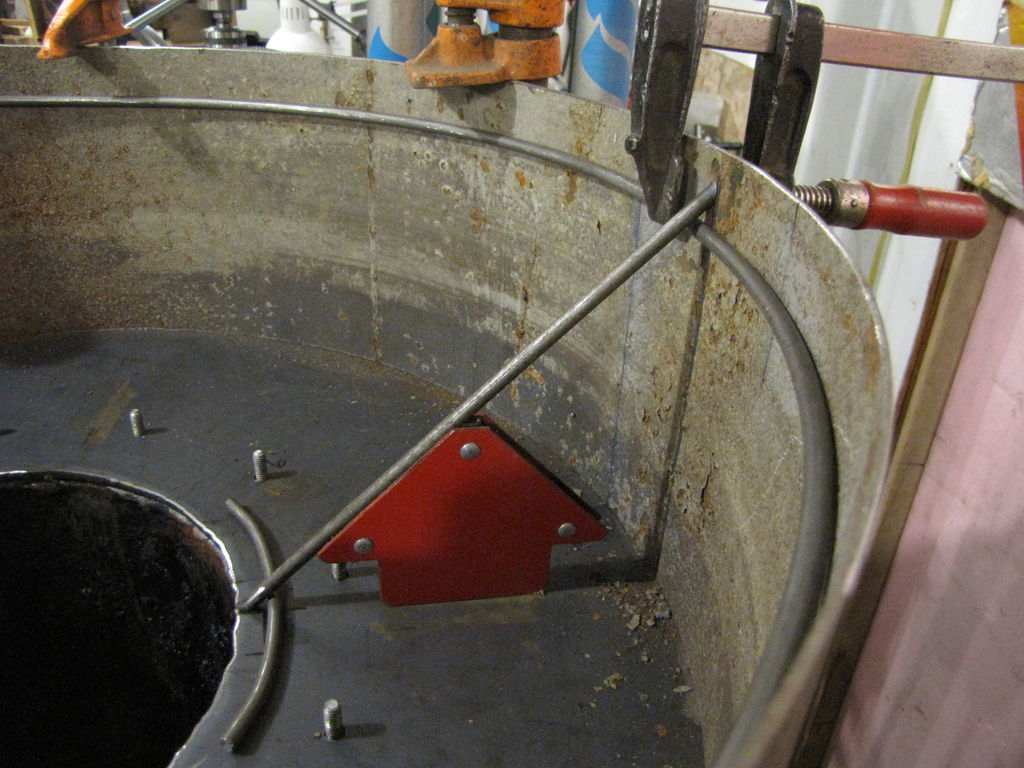
While putting my 10’ 1/4" rods away their flexibility struck me. Bend them into a couple of rings and cover them with spokes- sort of. So I used the 2 tanks in Pic 1 as bending forms. I just hand held them to bend and used a short piece of pipe to torque the tight bends at the end. I used the smaller tank to tighten up or adjust the curvature. Kept checking that back to the 24" form on the burner shell until I got it right Pic 2.
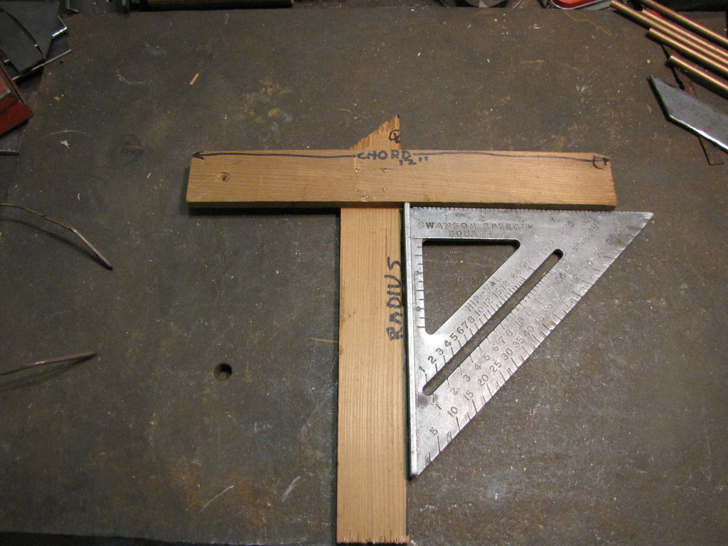
Pic 3 is my chord square. It can be used on either side but always line up with the pointed edge, this is the radius. The cross on the tee is a chord of a circle. Mark the exact center of the chord hold it to the curvature and measure to the shell wall. This will give you the length of the pointed section. The other part of the tee has an edge exactly on the center and perpendicular to the cross. We now have the perpendicular bisector of a chord which always goes through the center of that circle. The point is the center of the arc and lines up with my starting plumb line. This allows me to mark the edge of the firetube as a point on the radius line for the spokes. Gives a control for consistent placement of the spokes. This will become a cone grate. I’m thinking a 1/2" to 3/4" gap at the top ring and equally space the spokes on the lower ring. The bottom spaces will be smaller for sure. We’ll see.
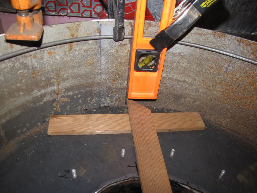
Pic 4 Establish a plumb line at your start point. Line up the point of the chord square on the plumb line and mark the radius line on the edge of the firetube. Both ends of the tee and the pointer will be touching the shell.
Pic 5 When finished there will be no shelf for fuel to snag on, just that 45 degree smooth slope. I’m going to fabricate the entire piece, then cut it in sections so it can be installed/removed through the fuel hopper opening. I got 10’ sections of 1/4" rod for about 4 bucks apiece.
Then on to the condensate moat and drain(s).
Feels great to finally get to some of this stuff.
Pepe

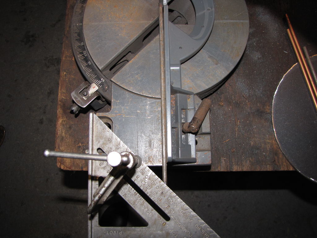
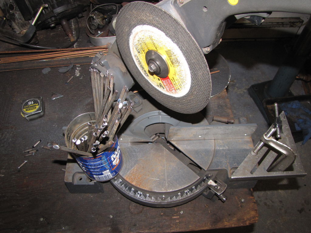
I set up and cut 45 “spokes” with the remaining rods. I cut all the rod 11" long with the same cut on both ends. Then I clamped my square to the saw with the 45 degree side against the fence. Then I slide the 45 degree end in to hold the cut end straight up and at my finished length and cut the other end to finished length. It’ll be back to the steel shop tomorrow for another 50’. It took about 45 mins. It’s hard to believe there are about 80 or so “spokes” with the 3/4" spacing. Bottom spacing is just shy of 3/16".
Pepe

Hello Fellow Gassers,
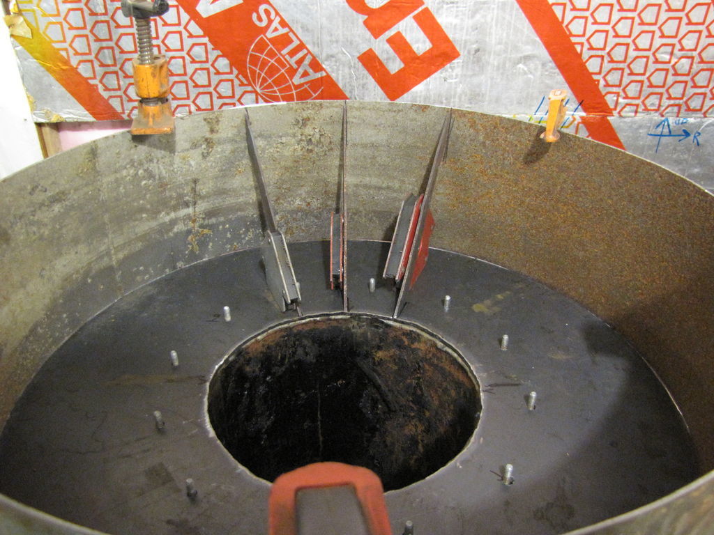
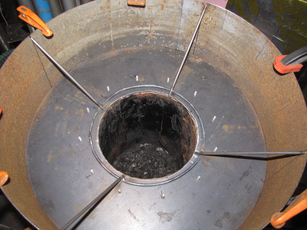
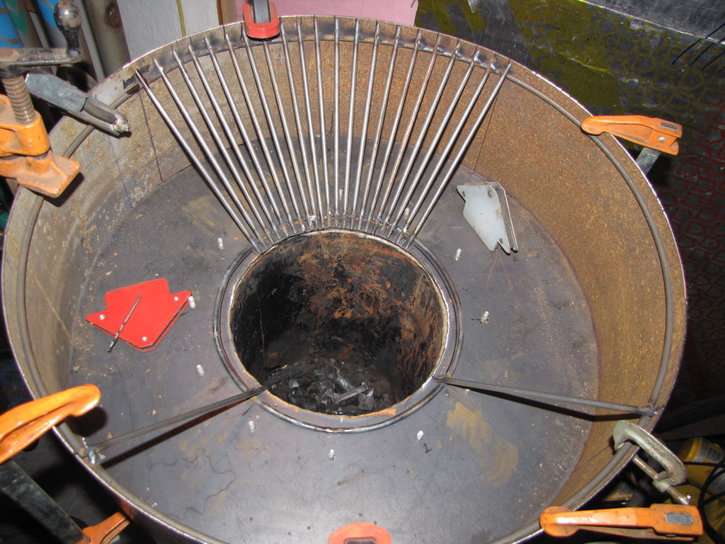
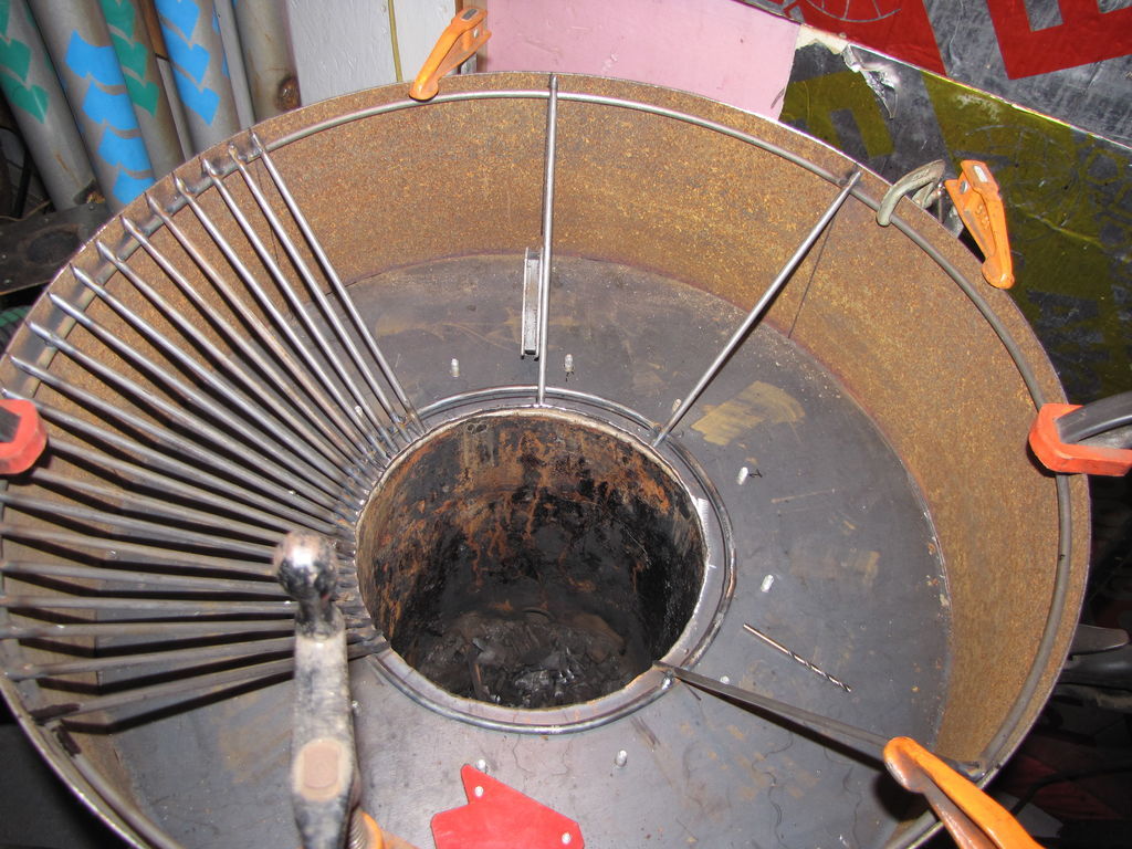
Pics 1 and 2 show the 4 spokes plumbed in at 90 degree intervals for a start.
Pic 3 Shows one 90 degree section finished. My spacings upper and lower seem to be pretty close to my calculated values. OK, so I put one spoke on the wrong side of the line. Jumped right out at you, right? lol.
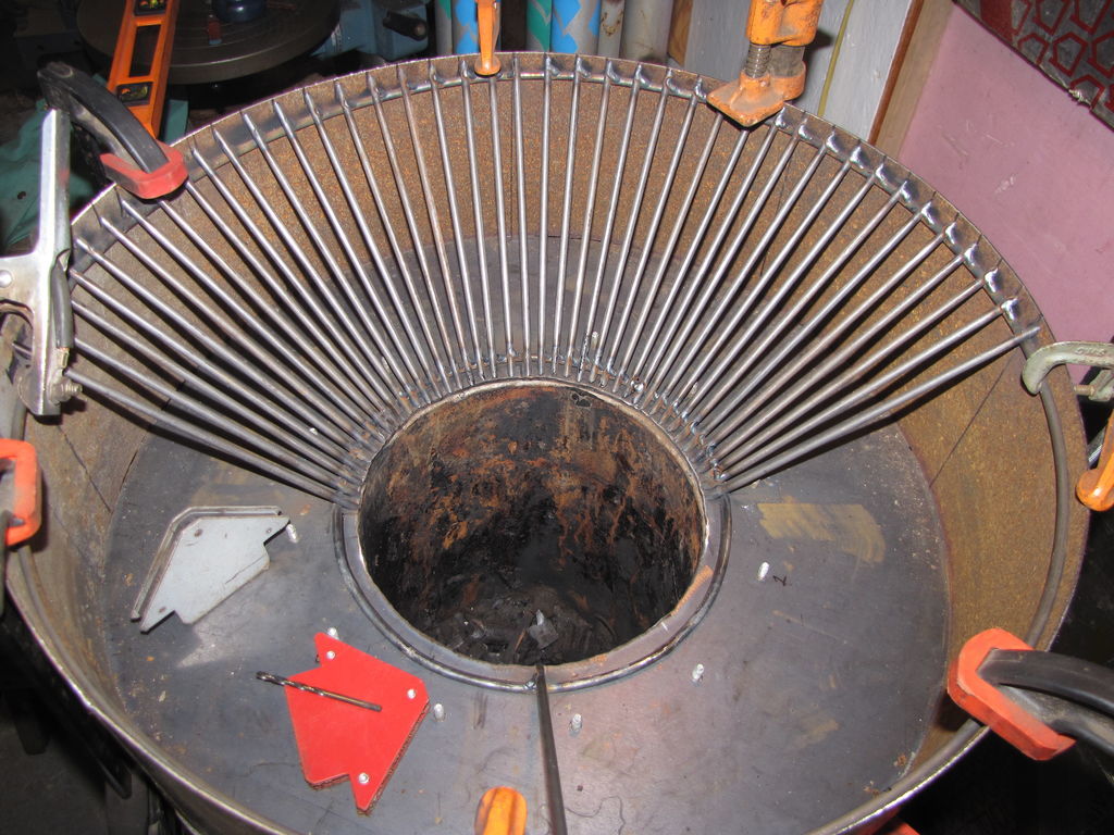
Pic 4 Shows the next 90 degree section but with an additional plumbed in spoke at 45 degrees to keep it running true.
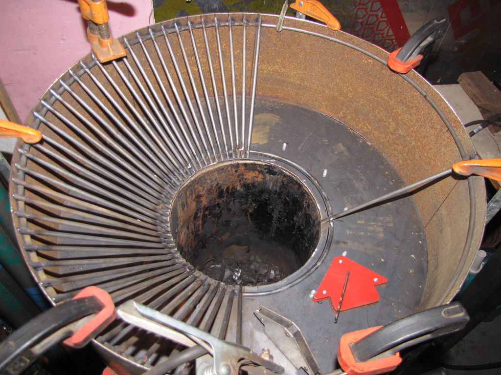
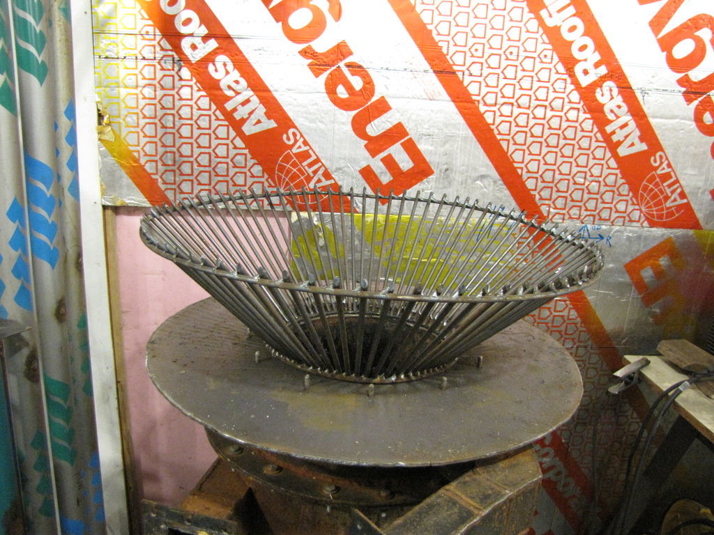
Pic 5 and Pic 6 Show the cone spokes half finished. I’ll put the retaining bead in front of the lower ring before I add any more spokes. I’ll plumb in a couple more spokes at the 45 degree intervals and finish this up tomorrow if I don’t run out of CO2/Argon.

Moving right along there Mr. Pepe
Hi Wayne,
Yes, it’s moving along on this fine sunny Sunday morning. Give us this day our daily bread, thank You. I had enough gas left to finish tacking in the remaining spokes. It’s not perfect, but betas are fit, form and function. I’ll look pretty later. Pic 2 looks way more distorted than it really is. It’s not sitting level on the base(operator error).
For those of you not familiar with the monorator hopper, some types of heat drive moisture(steam) up the firetube to the center of the monorator and fan out to the top, sides and bottom ledge under the grate cone where they hit these cool outer walls and the moisture condenses out to a collector for draining. With a 24" D top, 21" height and a 4 1/2" overhang my monorator has approx 16 sqft of surface area available with varying degrees of relatively cool surfaces. The overhang is not directly above the hearth heat stream so it remains much cooler, the design in action. I can’t wait to see it happen. The moisture condenses in a sort of drainable moat. The fuel itself also helps cool the gas by absorbing some of the heat to aid in drying. The heat releases moisture from the wood and cycles it up to the cooler surfaces via the forces of the center heat stream. There’s a lot going on here, hopefully.
Pepe

wow! First time I have ever seen anything SPOKEN into existence.
nice uniform work.
Thanks Wes, I asked my wife what the comment meant and she said, you know, Pepe, like a spoke? Duh. I can’t believe I didn’t pick up on it. We got a good laugh from that. Pepe
Hi Pepe;
This is looking good. Looking forward to results of your run. Dan