Thank you, JO. Are you off work this week?
4 Likes
Yes, I am. Only I just recieved a message I’ll be taking my mother to the hospital in Falun mid day Wednesday. Other than that I’m open for suggestions - as far as I know right now.
5 Likes
I was asked to become a reseller. I will search the email when i ger back home. Sure you can buy direct
5 Likes
Hi Jan, i found Hallant.se sells rebak in Sweden, can’t remember if thats the company i bought from, it was maybe 5 years ago.
I can’t find my brochure (im on Öland at the moment).
6 Likes
Jan, I could have used some help today. This was a little too much for my equipment. Three logs = full load 
Also, something drained the tractor battery and the low voltage made me unable to use the vinsch. A lot of non-productive work today.
Oh, and does anyone know why some slabs leave the log shaped like a banana? Has it something to do with if the log has started to dry on the surface?


14 Likes
I don’t think I’ve been of any help, I lifted in my wife’s golf cart over a week ago and have just started walking pretty well, had a broken back.
Do you have an electric winch?
Isent it “tjur” in the log?
11 Likes
I agree, tjur, it happens if the tree has been leaning and it tries to compensate on the opposite side. Like a humpback.
Sometimes it’s a lot and other times I don’t see a difference at all in the sawn bits. I haven’t kept track if it shows later on when it dries though, but some boards are surely by nature meant to be propellers.
12 Likes
No it’s hudraulic, but the electric solinoid needs proper 12V to do what I tell it to, via the remote.
Yeah, that was my first thought. But the slabs popped off like that on all sides. I was just interested to learn if there are other explanations.
10 Likes
I’ve slept on it, but I still haven’t come up with anything witty to say about propeller boards or the fact that Jan plays golf. That’s how slow I am.
12 Likes
I couldn’t help invade this thread when talk about “tjur”.
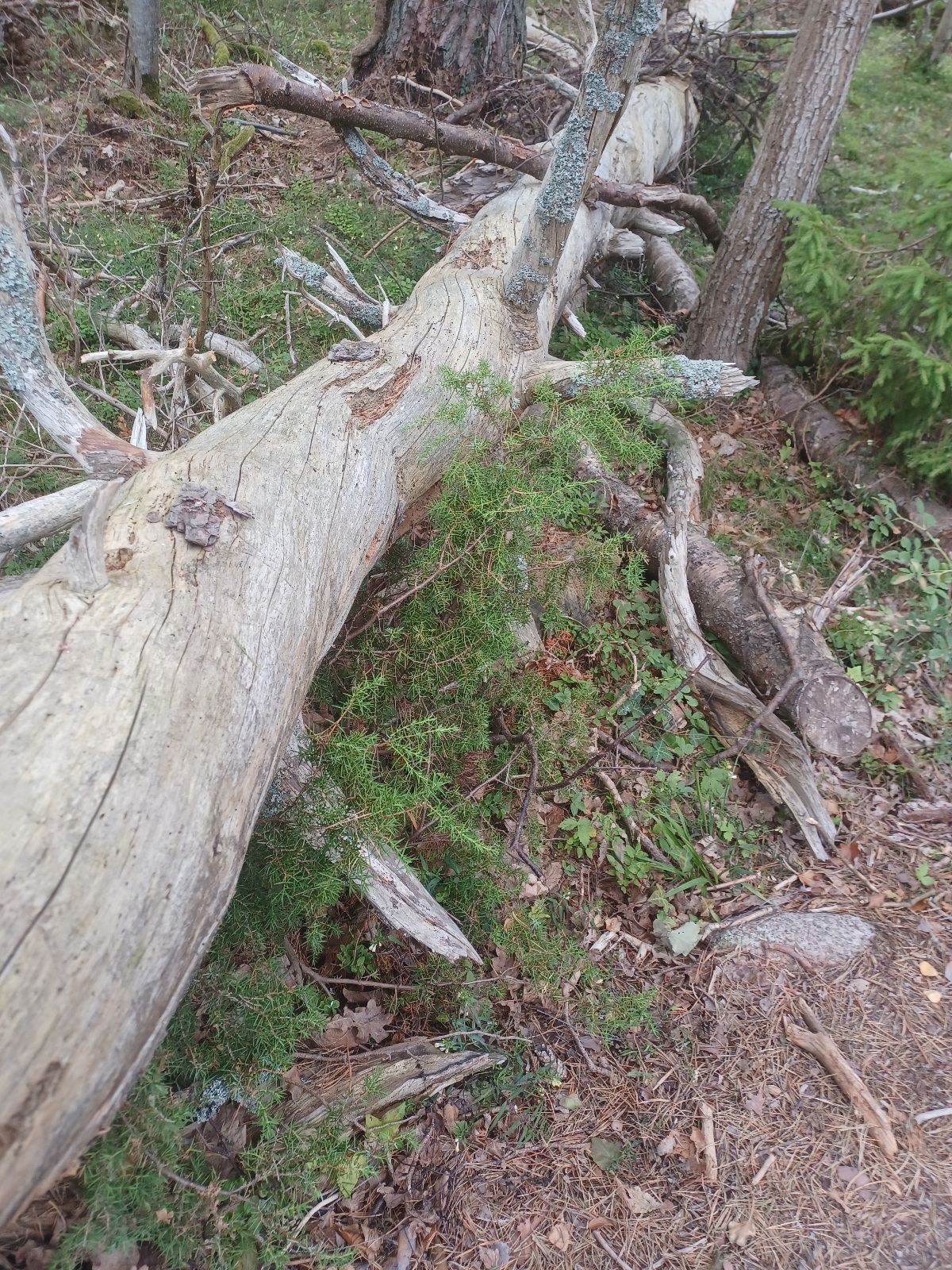
As walking in one of Ölands forest reservations i snapped some “educational” pic’s of “tjur” and “vres” that would probably make interesting boards.
In this case inflicted by storm and sea waves.

Straight pine, but look how twisted.
Another.
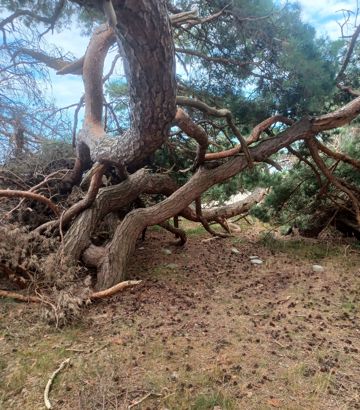
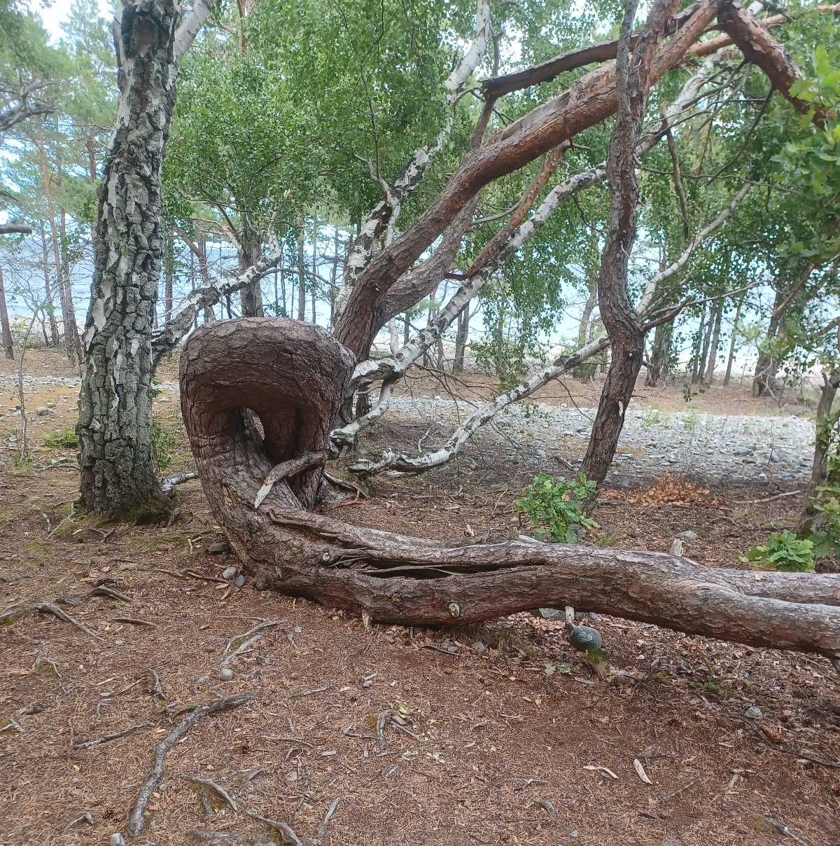
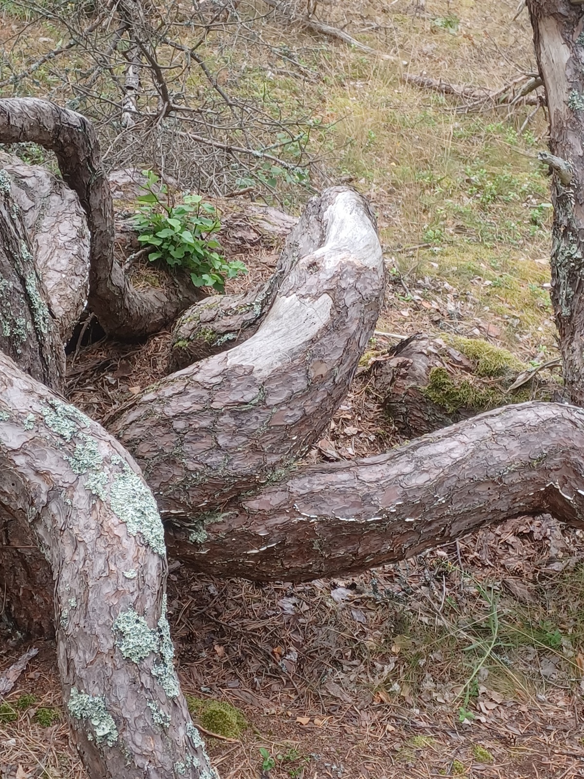
These are better intended for firewood.
But it’s fun to see old constructions where the builder used his imagination/artistic skills to make useful stuff out of wood like this.
Crooked and twisted wood pieces are often found in old, abandoned houses, saved as “spare parts”.
15 Likes
Cool trees Göran 
I tried to saw one straight but very twisted log a couple of weeks ago just to see how it would turn out but it was unuseable boards, completly ridden with cracks.
Are you calling my house abandoned? 
There’s plenty of bent pieces of wood on the loft in an old workshop on the farm saved for making sacrificial parts for horsedrawn sleighs, timbersleds and such.
13 Likes
Well, there are alot of bent pieces of wood in my place too, it’s just that the new generations seems to use that stuff for firewood as soon they move in in an old farm or forest place
10 Likes
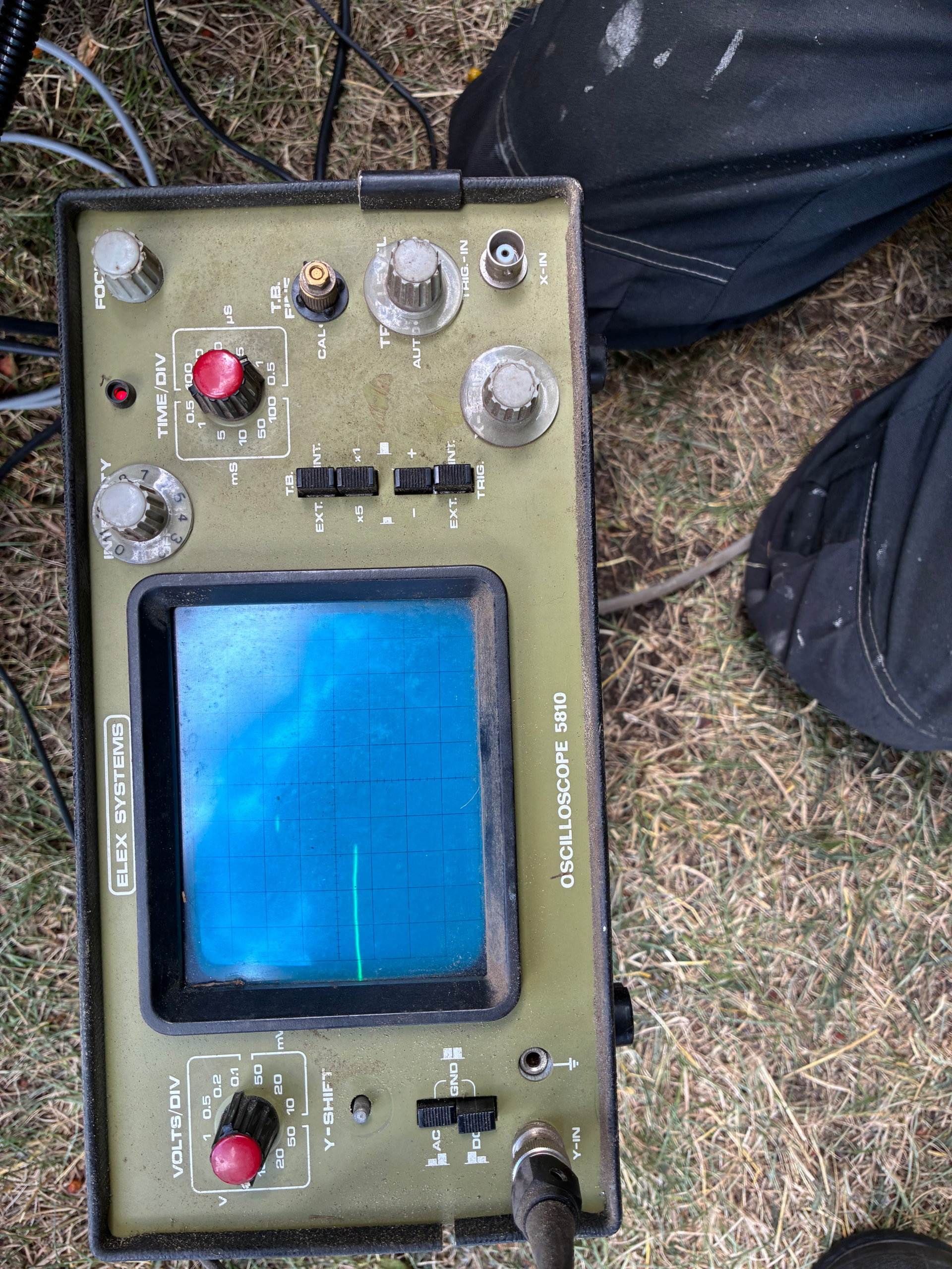
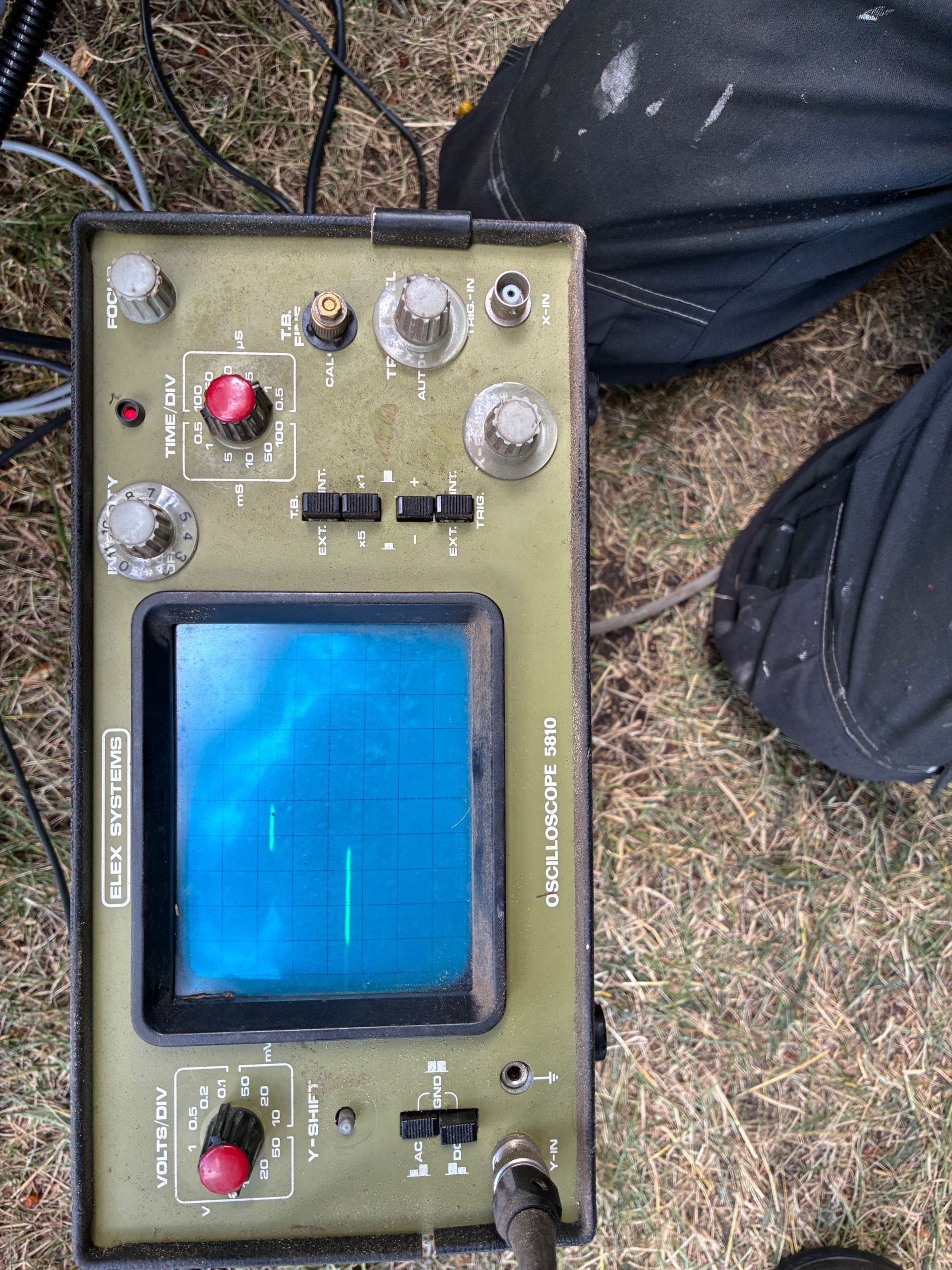
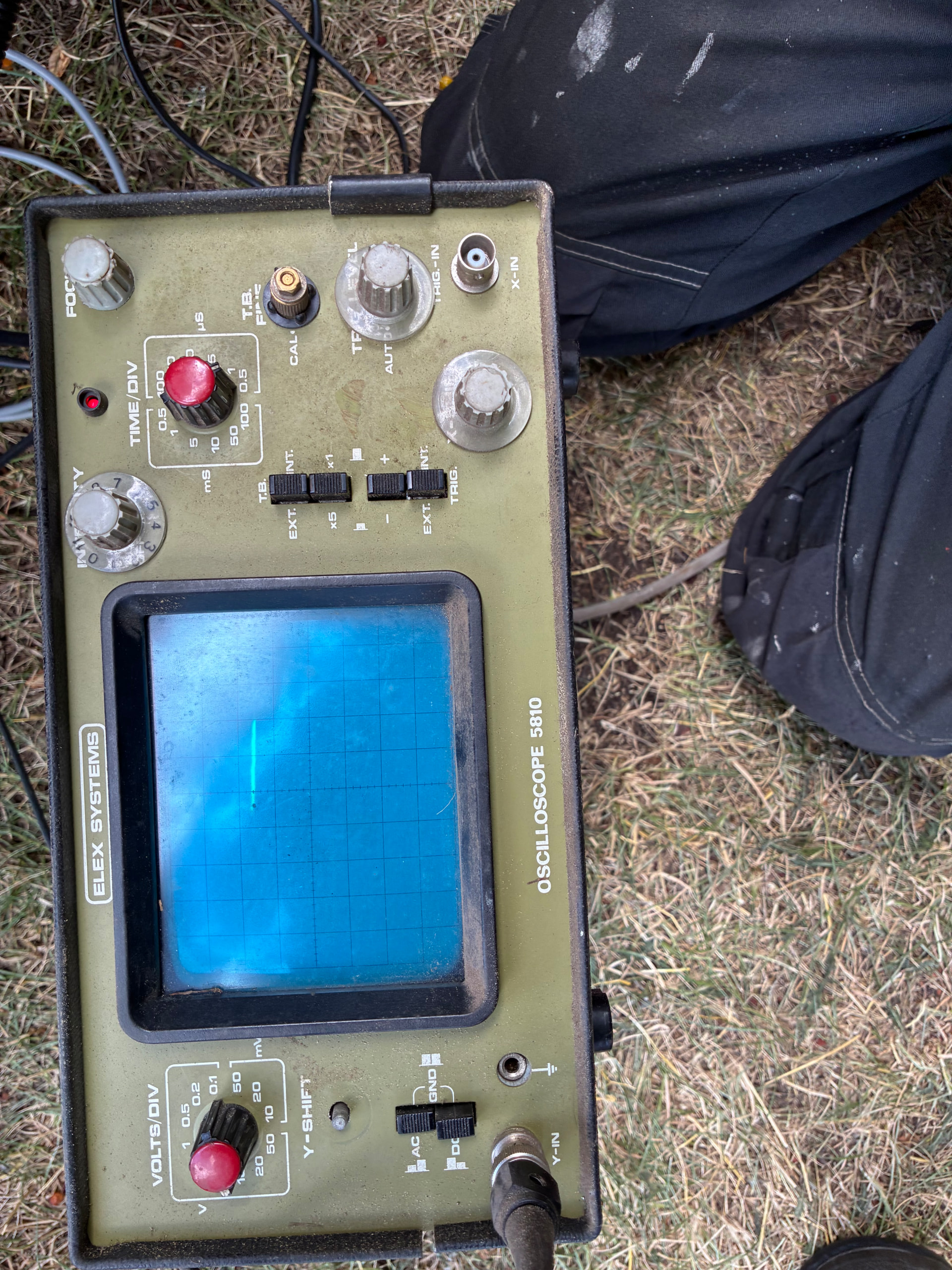
Does anyone understand how I should have the buttons on this so I can see the square wave from the crankshaft and camshaft?
Can I have the ground on the oscilloscope on the battery or does it have to be on the sensors?
6 Likes
Not me, I hardly know how to spell oscilloscope. 
9 Likes
Hi, Jan! I will explain it as best I can, may require coffee.
I am supposed to be Mowing the lawn, but it is raining, so here goes.  Second question first. You can ground your scope probe ground clip to any ground on the vehicle. It is always better to find a ground near the signal you want to view which minimizes the noise picked up. If you do not have a ground clip on the probe, you can use a wire into the banana jack with the ground symbol below it. That is next to the probe connector Y-IN (called a BNC jack). You could move the ground lead around for best results, short test leads are best.
Now, this is a single trace scope, but you can measure the time relationship between the two signals by viewing one signal and using the trigger input to trigger the beginning of the displayed line (Scope Trace).
The knob to the lower right of TIME/DIV says T.B.FINE. You should turn that counter-clockwise until it “clicks” into the “CAL” position. then, your time/div knob will be accurate.
Intensity and focus you know. TRIG LEVEL will be a useful knob to adjust as you measure. for most casual measurements, the trig level knob will be full counter-clockwise in “auto”.
OK. Now you have to provide an “EXTernal” trigger signal. (That can be your crankshaft signal). Ideally, you would have an additional probe to connect to the BNC connector in the lower right corner of the scope. If you have a fine solid wire that carefully will fit in the very center of that connector, you can run the other end to the crankshaft signal. The one ground connection should be sufficient, again keeping the wires relatively short and neat. You might want the scope up on the fender or something?
You will have to push-in the EXT TRIG button lower right, then adjust the trigger level until you see the signal from the probe input. The +/- is to trigger on the leading or trailing edge of the TRIG-IN signal. Return the TRIG. button to INT. for normal use.
The difference between where the trace starts on the Left and where the sensor pulse begins is the time difference between the signals, of course the crankshaft and camshaft are rotating at different speeds, and I’m not shure what this will look like exactly…
I know this is a lot to digest, take your time and play with the connections and scope time/div and volts/div. Learning by doing here.
Yikes!  I’m glad you have a scope to use! I’m happy to increase the confusion anytime!
11 Likes
Thanks, I’ll give it a try and see if I can figure it out and find a signal.
6 Likes
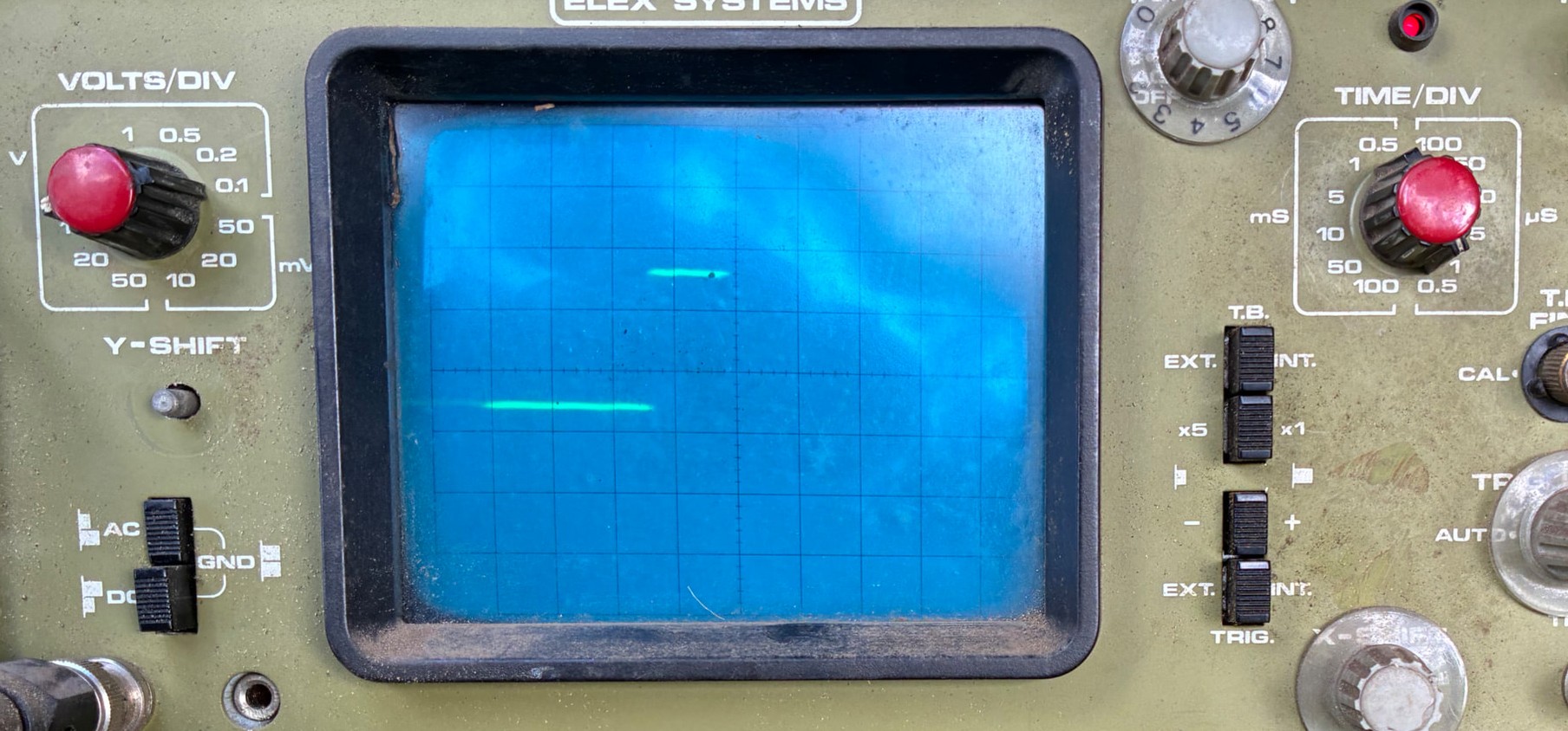
I thought, I don’t need to see both camshaft and crankshaft at the same time, I need to see a nice curve that I can take a picture of.
and the best I can get is what you see on the oscilloscope, don’t know if it’s wrong with it or wrong with me?
5 Likes
It looks like it just isn’t showing a vertical line. try disabling the triggers, and set it to auto. Then use the vertical (voltage) and horizontal (time division) to see if you can pull it up on the screen. It may just be going to fast for it to draw according to AI..
The best way is going to be testing it with a signal generator, which you can make from an esp32 and there are numerous projects you can copy code. or they are like 10-20 bucks off ebay/amazon, etc. This gets you used to adjusting it, and verifies the scope is working.
The other issue you may have is you may need to compensate the probes. I think this video is trying to go through many more details then you want.
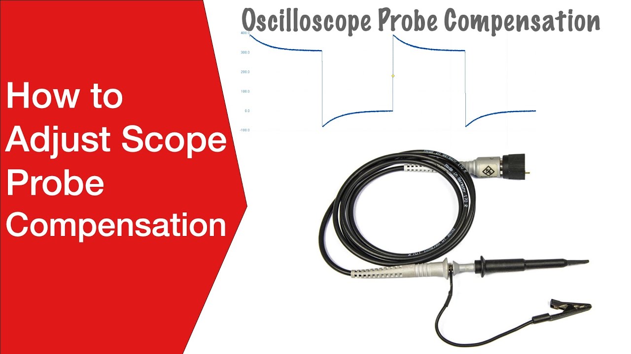
You can get probes off amazon/ebay, etc for like 10 bucks but make sure the bnc connector is the right size. I dont think they are different but I truly don’t know. It is easier to measure first. 
Surprisingly I couldn’t pull up a manual or schematic for that particular scope with a quick search.
7 Likes
Jan, this is about what I would expect from a crank or cam sensor. It is being read by a computer chip, so a fast on/off transition is expected. Your scope is on a high-speed sweep (one Microsecond per division?). anyway it would be a pulse like this rather than a curve.
9 Likes
It woud be the right waveform for a single square wave without the vertical.However the voltage knob appears to be pointing at .1v per division, which means it is .2v differential. but if you look at the ground push buttons it is set to AC, which I am completely guessing that needs to be set to DC if the probe has a ground on it, or both buttons up, it uses what is in the ground input.
Or do you have to compensate for the probe, like it could be a 10x probe so the .1v is really 1v, which makes the signal 2v, which seems weak, but that could be a ground issue.
6 Likes