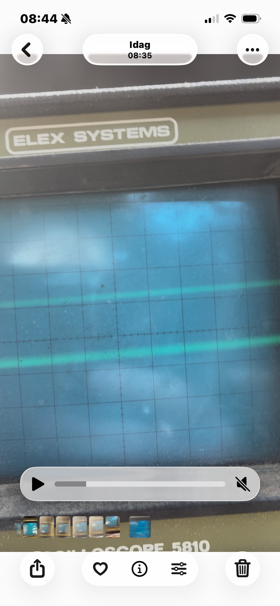
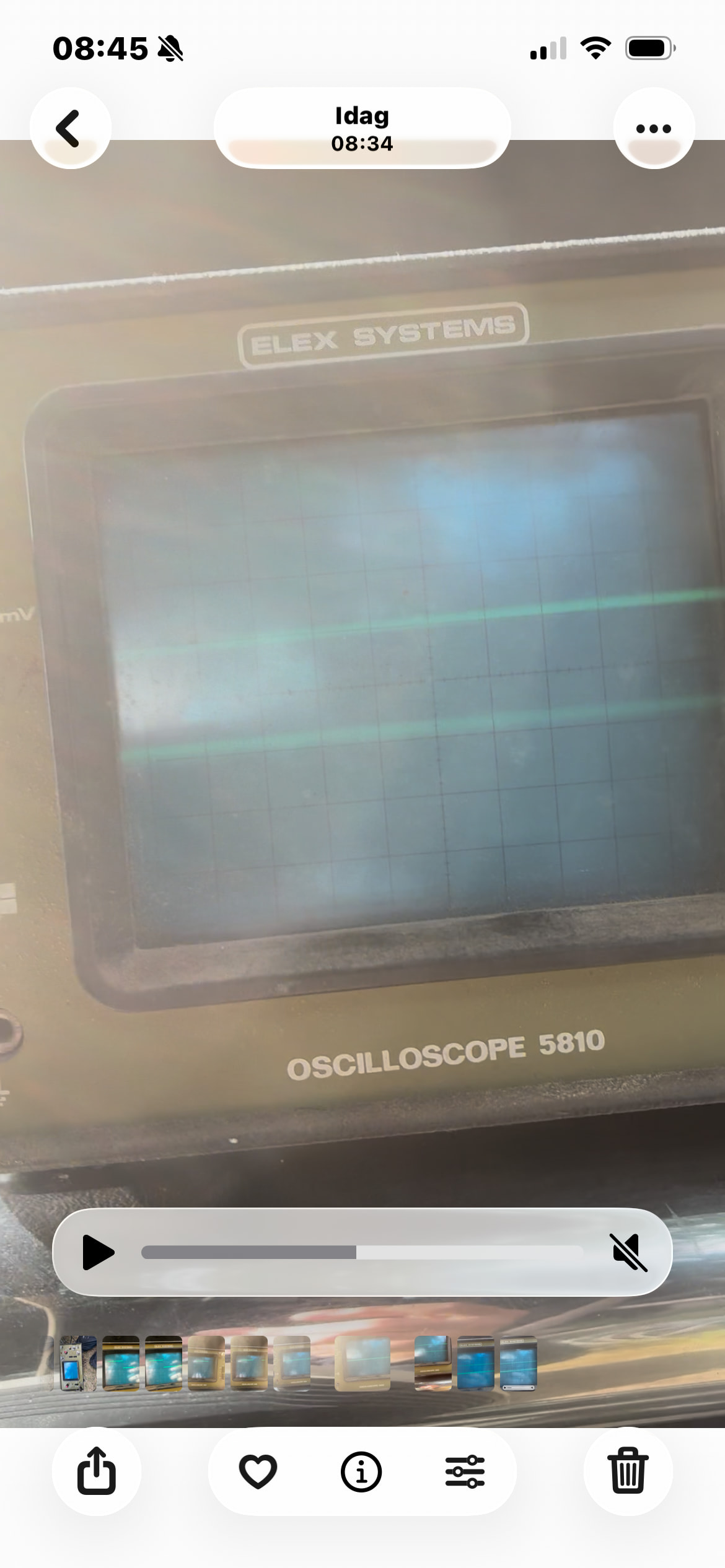
I tried a little different this morning and got a little different both lines and slanted lines that wander across the screen, now I’m wondering if I’ve messed up when I don’t use the shielded cable, I’ll test this, there’s one for the crankshaft.
6 Likes
it could be shielding or grounding. if it isn’t that maybe you nudged the time/div (horizontal) knob?
5 Likes
Jan, you may have to adjust the Trig Level, Time/ Div, and maybe Volts/Div. In the original photo, I believe your Volts/Div is on 10volts, maybe try 5volts/div. Try the buttons near the probe connector on AC and DC. You should be able to adjust the trig level and get something to sync up. I can’t see the knobs in the latest photos, make sure your TRIG. button is pushed in for EXTernal sync if you are using that second connector for a sync signal, and button out for INTernal sync if you only have the probe connected by itself.
It’s a learning curve, but worth the trouble. 
Also adjust the TIME/DIV slower or faster to get a signal that looks proper.
10 Likes
Jan, did you mention the reason you wan to take a look at those signals? Maybe I missed that part.
11 Likes
No, I haven’t mentioned this, but it’s so that I can understand how and if I can adjust the ignition so I don’t have to worry about the puffs.
8 Likes
Nice work Jan, keep on experimenting 
You have good support here.
I haven’t chimed in any, because im really “rusty” on using oscilloscopes, it’s some years since i used one, and no way i could explain it understandable over the net or telephone, i would only help you make smoke coming out of that scope…
But this is interesting to follow.
And by the way, you may put a simple sensor somwhere, on crank pulley for example, to get a nice reference signal.
10 Likes
If the voltage is rising really fast, it’s hard to see the line. If you increase the intensity (brightness) until the horizontal or sloping lines are too bright, the vertical trace will often be visible.
Often the DC button is a direct input from the probe, the AC button will include a blocking capacitor in the input circuit so DC and slow AC signals are suppressed, letting you see a small AC signal on top of a large DC signal (offset). Both buttons will ground the input, so there’s no voltage displayed, so you can set the zero level on the screen.
Anyone have a guess as to what kind of sensor this is? That’s a pretty clean, square pulse for an inductive sensor, which is what I would have guessed.
9 Likes
Oh thanks for enticing me to look that up. what I learned was Jan needs to zoom way out. 
I pulled up this video which isn’t what I was looking for but he goes through testing the two main kinds of position sensors. I am guessing it has the 3 wire 5v style. What I didn’t realize was there were several teeth it interacts with that aren’t spaced evenly, and there is a gap in crankshaft signal every 360 which means it is easy to see the rotations on screen on a scope.

I was looking for a crank and camshaft scope outputs like Mike was trying to describe. I haven’t found one with an analog scope. This is a pretty decent video using a two channel scope but it is digital and fancier. but he sets up a scope, and then they are looking for known good patterns to compare with. Which should be visible with an analog scope.
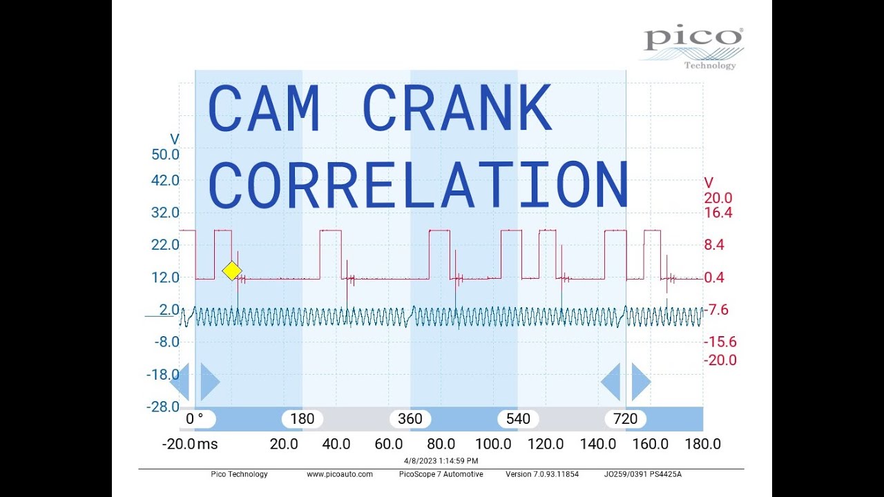
From AI.
Signal type: Hall-effect style digital square wave switching cleanly between near 0 volts (low) and 5 volts (high reference pull-up).
Transition quality: Edges should be vertical and flat-topped; rounded or noisy transitions indicate a weak sensor or a bad ground.
7 Likes
Yes, just like usual, if I had had almost any other car it would have worked to set the ignition earlier, but not the S10 GM.
2 Likes
ahh! I think this is the issue. There is a timing sync wire. which is probably an emissions rule to prevent people from trying to bypass the emissions rules by messing with the timing.
From AI. (and i always forget what year your truck actually is.. so this is for a 95..and gotta love how it adds a generic amazon product search link in for the timing light.)
AI Overview
To change the ignition timing on a 1995 Chevy S10 (whether it has the 2.2L 4-cylinder or 4.3L V6 engine with a distributor), you must disconnect the computer advance wire, loosen the distributor hold-down clamp, and rotate the distributor housing. [1, 2, 3, 4, 5]
Preparation and Tools
-
Gather a timing light, a distributor wrench or appropriate S-socket, and chalk or white paint.
-
Warm up the engine to normal operating temperature, then shut it off.
-
Locate and disconnect the BYPASS/set-timing wire (usually a tan wire with a black stripe). On many 1995 S10 trucks, this single-wire connector is taped into the harness near the passenger-side floorboard/kick panel inside the cab, or under the hood near the firewall. Disabling this prevents the computer from fighting your manual adjustments. [1, 2, 3, 4, 5, 6]
5 Likes
Well, I have a 1995 S10, but it has most of the parts from 1996, which means the distributor is fixed.
Then I have a 2002 S10, which has ignition controlled from both the camshaft and crankshaft if I understand correctly.
4 Likes
That is emissions rules. From what I pulled up, they are both completely controlled by the computer. It looks like you need to reprogram the ECU with something like HP Tuning software.
What you are trying to do is trick the computers by altering the sensors which may or may not be possible. It is frustrating when it is literally like 1 adjustment in expensive software that they may have cracked down on…
2 Likes
The problem is that GM has its own system with the crankshaft so nothing that exists (as far as I know) fits, otherwise it would have probably worked.
2 Likes
No parts needed. They do it all in the computer. The government cracked down on it. I think they can take your mechanics certification and fine you like 2k per modified vehicle. Then they went after makers of various performance tools.
You might find this thread interesting. They are talking about using free tools.
https://www.s10forum.com/threads/getting-started-with-free-open-source-pcm-tuning.866113/
4 Likes
12 Likes
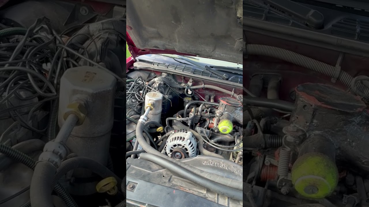
Strangely, when I was out riding last time, I stopped and looked at some wild boar tracks, when I was about to leave, I couldn’t get the car to start on gas, so I went on petrol and tried to start on gas, finally I got it to start and then I had about 3 times as much air as usual.
Do I have a leak that I’ve suspected for a long time that suddenly became tight or what could be causing this?
7 Likes
Did your filter get clogged? I could see like vildman, Snömannen, and even trolls getting upset about you stalking their food source, and throwing rocks or something.
Or maybe just sitting there hot and idle, increased the size of the charbed.
4 Likes
No, it’s the other way around, I had to give it 3 times as much air for the engine to run well, I suspected I had a leak but couldn’t find anything, I’ve thought about the filter cover, but it’s hard to check.
4 Likes
It does sound like a leak.  Did you just pop the filter cover off, maybe clean the filter? You might find a gap in the seal, or it just reseats itself.
4 Likes
I’ve taken the filter out a few times but can’t find anything wrong, and the water in the radiator after the filter is completely clear, so I think the filter is good.
4 Likes