Nozzles for Charcoal gasifiers, part 2

Hi Bruce,

The 40 mm vacuum has been so far the best value to perform the small engines under load.
The less vacuum = more gas can flow at the same stroke length
or; less restriction between the engine and the gasifier… hence better power output.

Grain size of the charcoal, even spread from small to big pieces… everything plays a role…
Make it easy breathing is the best way to succes.

I will put this to the test with the gas analyser, different nozzles sizes with same suction/airflow pump, so we can learn about it.

7 Likes

Hey Koen, thanks for the info. I think I might take the opportunity to see if I can confirm your findings by adding a simple “pressure gauge.” Should I take my measurement at the outlet of the fuel hopper so that I am also taking into account the friction of my filter and plumbing?

The general idea is to add a port with a water filled loop of clear hose, and record how much it rises from the static level, right? I had meant to do this at some point anyway, and it would be interesting to see how the pressure changes as I drill the hole larger. I will do a retrofit when I get a chance, but I need to get my charcoal grinder up and running too.

9 Likes

Koen,

Thank you for sharing your expertise and lab equipment with us.

8 Likes

Hey all, I added a water gauge to my cyclone yesterday, and I ran some tests to see what sort of draw the engine is producing. Here it is after the run, the water level has dropped a little bit from my bottom mark, perhaps due to the hose shifting its position. Therefore, the measurements may have a little bit of slop in them (~5mm).

After getting the engine warmed up, here was the draw at idle (3600rpm). I measure it at about 3/4" (19mm).

When I connected a 600 watt load, the vacuum increased up to about 1 1/4" (32mm). RPMs dipped to about 3500.

Assuming my numbers were low by a few mm, that suggests that I am probably pulling in the neighborhood of 35mm of water column while under load. I am surprised at how close that is to the 40mm number provided by @k_vanlooken, given the small nozzle I am running. My question then becomes, if I wanted to increase the suction, wouldnt making the nozzle hole bigger actually reduce it? Like covering up the end of a shop vac nozzle increasing the pressure in the hose? If that is in fact the case, should I be thinking instead about trying to reduce the friction in my filter, hoses, and mixing manifold?

I cleaned out the hopper to work up the mounting hardware for the cyclone, and the nozzle still looks exactly the same as when it went in.

5 Likes

Is it possible to get a vacuum reading between the filter and the engine? I’m still not sure where Koen is taking his vacuum reading and how much pressure drop there is across his filter.

2 Likes

It would certainly be possible, but it would be a bit of work -I would probably want to build another water tube. I could use the blower fan and test it with and without anything in my filter - that would give an approximation of the resistance of just the filter media, but it wouldnt measure the drag from the hoses and such. Edit: It is currently still cooling down, or I would go out there and give it a try right now.

3 Likes

Thanks for considering a test across the filter. Your good work is really helpful.

1 Like

Carl; I believe you are reading your monometer incorrectly. When you start with no vacuum, the water level in both legs of the monometer should be at the same height. When it is pulling a vacuum, you read it by measuring the distance between the two water levels. From what I see in the picture, you are pulling more like 3 inches of water. TomC

6 Likes

I see! That would explain why the readings were so low even with the small nozzle. I will run some more tests tomorrow, and see if I can get some better data. Another fine example of why you shouldn’t just assume you know how something works! :grinning:

5 Likes

hi Carl,
To measure the difference between the 2 sides of the tube.
if the left goes down, the right goes up. measure the distance (vertical) of the 2 fluid levels

edit: Tom C beat me at it

4 Likes

Here are the parts I plan to use for a gasifier nozzle to power a 200cc cargo trike in Rwanda. 15 mm tungsten carbide nozzle screws into a Stainless 3/4 -1 coupling. Street 45 degree connector. Cross fitting for EGR and H2O drip. Flexible shaft for nozzle clean-out. The reactor body is 10" ID X 36" insulated chimney pipe.

I figure the insulated reactor will need some extra cooling.

8 Likes

I like the baseboard radiator/cooler setup. I think I have some pieces
around here to put to use. I’m thinking their efficiency will give my
future cooler a smaller foot print and height.

2 Likes

Very nice Bruce. As an aside, inspired by your MG project’s hydronic baseboard cooling system, I’ve also started using these, specifically the clamp-on style.

What I’m using is similar to this product from Fabtek

which uses 3/4" pipe and dissipates a (potential) max of 591 BTU per linear foot. The 1-1/4" pipe version dissipates 1527 BTU/ft, even better (and less restrictive). Caveat: the price for this stuff seems to be increasing a lot lately.

4 Likes

I plan on twisting a long strip of 1/16" X 1" copper to go inside inside the 1 1/4 pipe to create turbulence. I think the turbulence will give better heat exchange than a normal laminar flow.

4 Likes

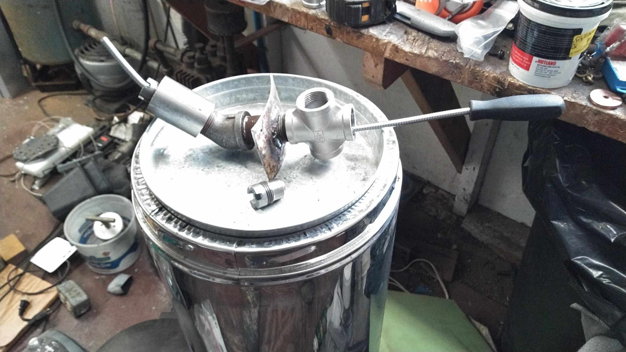
Okay, round two of pressure readings on the small orifice (11/32") Leitinger nozzle :grinning:

First off, I had a strange mis-match in my water levels, about 1/16" that would not go away no matter what I did. I am not sure how to explain that, so all measurements are +/- 1/16" I guess?

@bsoutherland: I did a test on the filter resistance, and found it to be quite small. Here is the initial reading, with the fan pulling just shy of 1.5" of water through the filter. I figured that would be a good value, as it is what I will be shooting for with the engine draw.

Next, I pulled off the wool sock filter, and removed the wool batting that fills my ammo can.

Overall, my filter is reducing the suction by about 1/8" of water column. I cleaned it out - it had a little dust in the sock - and ran it again at a lower draw and got the same results.

Next i fired up the engine and took some readings of it during idle and under load. At first it was drawing about 3" at idle, but after maybe 5 minutes of warm up, it had settled down to about 2 1/4".

When I connected the space heater, it pulled a little harder, rising up to about 2 3/4"

I am curious about the drop in pressure as the engine warms up, any thoughts on that?

Seems like the takeaway here is that I am indeed choking the engine- it draws 57mm at idle, and about 70mm while at its maximum load. I think I will try boring the nozzle out to 1/2" next, and repeat the pressure testing at idle and under load. I will also check and see if that will give me more power to work with.

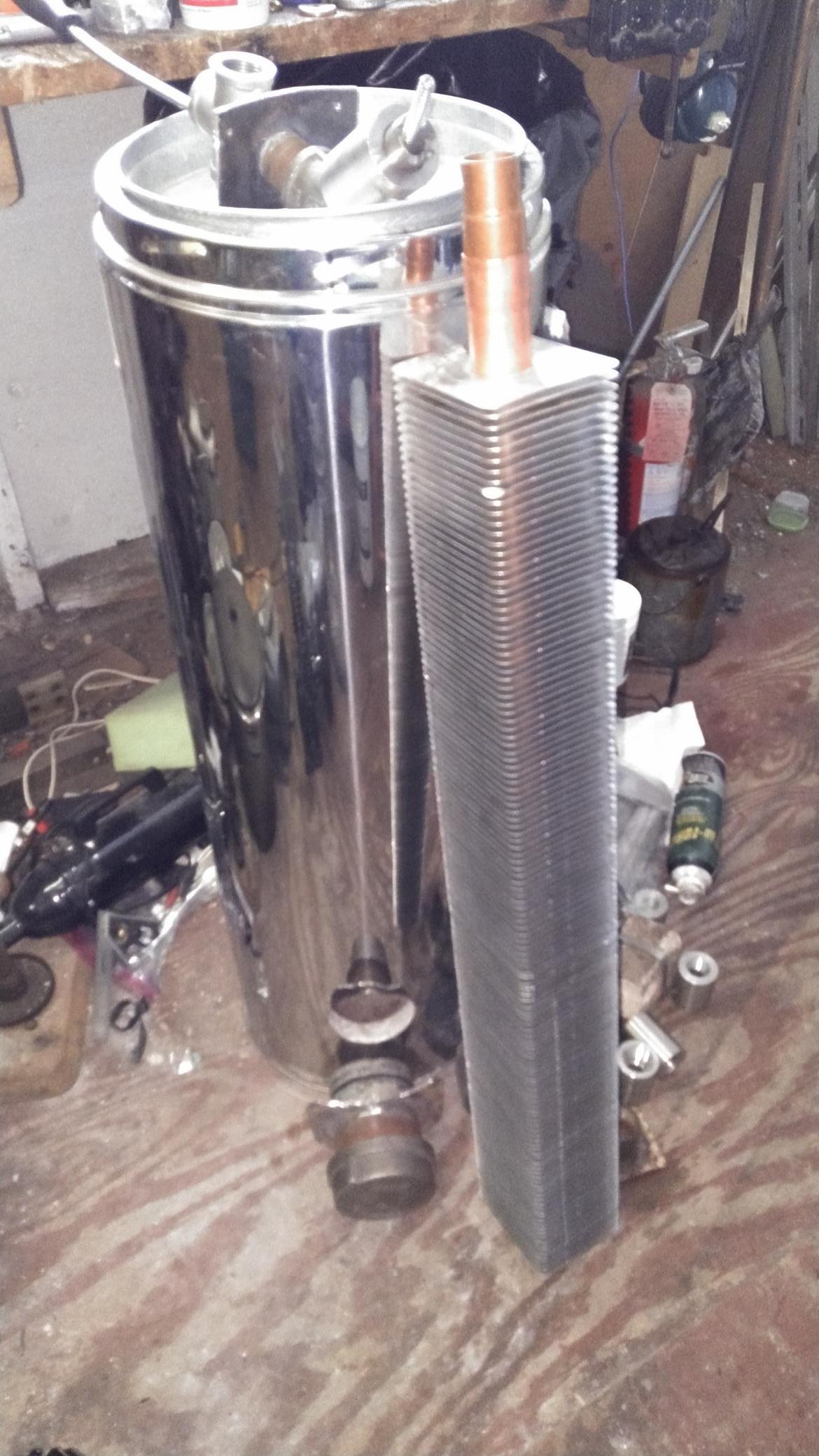
I figure while I have it torn down, I will also add an EGR system, and maybe slap some cooling fins on the sides of the reactor.

4 Likes

It will do that. Most residential hot water heaters have a ‘spinner’ in the center tube. I am trying to go one better and make my heat exchangers both spiral path and counter current. But not yet up and running.
Rindert

2 Likes

Hi Carl,
Don’t change more then one setting at the time. Then you learn most of your gasifier.
Stick with modifying the nozzle size alone at first. Then ad egr and test again
observe every little step you make and the outcome from those.

6 Likes

That is a good design philosophy - I was thinking of just welding a section of pipe to my nozzle while I had the whole thing torn down anyway, and then testing the actual EGR later.

What are your thoughts on cooling my reactor with fins? It gets up to about 400F when running, which should not pose a problem for any of the materials, but just seems too hot to me. I suppose for a stationary application it doesnt really pose a fire risk or anything, and I could always put a cowling around it to keep fingers safe. I guess I will hold off on modifying it for now, and see if the change in nozzle, or EGR can eventually bring that temp down on its own.

2 Likes

if you can keep the heat inside the reactor , not pulling the heat ou by the walls, the gas gets better… and less Co2 in the gas
a nozzle protruding a bit further inside, a nice balance in corn size charcoal… fine and coarse mixed well…
Works a a charm…

3 Likes

In post 184 the picture shows the tie strap holding on leg to be putting a crimp in the tube— possible causing this discrepancy

I know the amount of time the vacuum runs high on start up, seems rather long, but every engine has to warm up the oil, and bearings, etc. During this time the governor is trying to hold a certain RPM. During this time there are drags on the engine that slow it down. To keep the RPMs up the governor opens the butterfly in the carburetor. The butterfly restricts the vacuum that is pulled on the venture of the carburetor. So as the butterfly is opened by the governor, more vacuum is pulled on your manometer. More simply, if you open the butterfly all the way, you are removing the restriction that it causes and you are directly reading the vacuum pulled by the piston. ( I think ) TomC

2 Likes