Wow thats too cool. I hope to preswade the surgeon to take some pics if l ever need a surgery again 
4 Likes
Hey Koen, sorry to hear about your hand, and im also sorry that I looked at the pictures 
I suspect that you may be right about the generator not being “quite right” as I also find it strange that I can drag the voltage way down without seeming to bog down the engine. It also tends to produce like 130+ volts when its idling, so maybe that would be worth checking out.
Unfortunately I never did run any tests with it on gasoline, and after a backfire during my early tests with woodgas, the carb has not seemed to be working right. I am not really sure where I would start in trying to track down that problem, as I am really not all that knowledgeable about gas engines. In fact, at this point I probably know more about running on charcoal, and my expertise there is clearly quite limited 
There is a set-screw on the carb to adjust the idle, which I have not fussed with, but I did make a point to observe the governor on my last test, and it was moving to WOT when I applied the load. I can not say for certain if that was also the case when running a smaller nozzle hole. It was however a lot harder to get it to maintain 3500 RPM with the larger nozzle.
The charcoal seems to be fine, i finally have a supply of dry graded fuel, and if anything it was faster to flare with the larger hole. Flame has always been blue. The first puff of gas to come out of the blower sometimes appears hazy, but it quickly becomes invisible. The slag from all of my runs, regardless of nozzle size seems to form a glassy cone. I have yet to find any ash, or crumbly white powder that is not fused together.
What it seems like you are saying is that while this engine should maybe be capable of putting out more power, it is hard to gauge how much any percieved lack of power is due to the gas and how much is due to the condition of the engine? Are these small gas engines already a little low on compression for charcoal gas? I also cannot say for sure that this particular one has not been abused. I feel like I remember that someone mentioned that OHV engines were able to produce a bit more power than a regular flathead - anyone have thoughts on that?
I am fairly confident that the system is not leaking, and producing good gas, so I think I might try and build up the hole and re-drill it. I will maybe test something halfway between my starting point and where I am, and see how the output and vacuum respond.
3 Likes
Hi Carl , would it be too much trouble to strip the carb off the engine one day while its not being used and give it a good clean, there are plenty of you tube video’s out there on most types of small engine carbs clean ups showing what to do and what to look out for , at least then you can try running on regular fuel and compare the drop when on charcoal .
Dave
3 Likes
Hi Koen, continue prayers for healing and rehabilitation of your hand. In Jesus Name.
Bob
4 Likes
Hey Dave, I think I am going to give this a go - but I didnt have any gas on hand today. I read up on that particular carb, and it dawned on me that the adapter plate for woodgas that I was trying to run it with might be blocking one of the breather ports. It is on my list to put it all back together in the stock configuration and give that a try.
When I took the carb apart today, I did find a piece of wool batting had been sucked in and gotten snagged on the butterfly valve. I wonder what would have happened if it had made it all the way to the piston… I decided to see if that could have been a factor, so I started up on charcoal, and loaded it down. Output was still weak, about 450w, 100-105v, 50-60 hz (the meter doesnt show the actual value, but switched back and forth between those), and the rpm was about 3300.
I did adjust the idle screw a little bit, and that brought the idle voltage down to about 120. The generator does not have any way to adjust the voltage that it produces, which does not surprise me, as its a pretty cheap and simple machine.
A thought occurred to me today too, and that is whether the spark plug gap will have any effect on the engine performance? I need to look up what the stock gap is, but am I right to think that a wider gap is going to delay the spark by a little bit? Would a smaller gap give any advancement on the timing, or is it not worth messing with?
2 Likes
Hi Carl , there was talk years ago on spark plug gapping to aid advancement and indexing the plug so that the gap at the end of the electrode is facing the inlet valve , and i tried both so it should not hurt to try ,but i think the only real way with noticeable affect is to try advancing the timing the normal way .
I still think you need to run it fully of petrol and see just how much that unit will provide of usable power before dropping off and then at least you will know if its the fault of the charcoal and to start investigating why .
Dave
5 Likes
Okay, i gave the carb a bath in some gasoline, poked out all the holes i could get to, and put the whole thing back together the way it was when I got it. (except one extra bolt that i am still not sure where it came from).
To test I used a shop vac which pulls 950W out of an outlet on 122volts, and heater with 2 settings: 650W low, 1400W high.
Running on gasoline the generator wanted to idle at like 3800RPM and was putting out about 140v ac with no load. So yeah, voltage regulation is … spotty. Anyway, I plugged in my loads, and recorded the wattage and the voltage as I upped the load.
800W - vacuum cleaner - 117V
1300W - vacuum cleaner, heater on low - 111v
1700W - vacuum cleaner, heater on high - 103v
At that point I called it good, because 103v is already a bit too low, I think. It seems like the fact that RPM and voltage are linked, you would be very hard pressed to make this thing just stop dead in its tracks. As you load it down more, the voltage drops with the RPMS, and the lower voltage reduces the wattage of your load. Resistive loads wouldnt care, but more sensitive equipment might not like it.
So, I think I would call its effective wattage somewhere around 1300W on gasoline. Seems like I will be lucky if I can get 650W out on woodgas? My current setup seems to top out around 450, so I feel like there is room for improvement.
6 Likes
Carl it seems that your not a million miles off the max you could really expect on charcoal anyway , so you may as well play a little trying to get more out of it advancement and water drip could help a lot , but in the mean time keep a look out for a larger output generator ,maybe one you can buy for spares or repair just to keep the cost down .
Dave
2 Likes
This is what I use to adjust my generator. As the generator loads down, the Hz may change. So I adjust the generator to the load that’s needed, always matching as close to 60 Hz as I can.
5 Likes
Rule of thumb, for every .006 of an inch you shave off a key and turn a flywheel you pick up about 1 deg of timing.
But that is a rule of thumb and you need to measure and test with a timing light.
You can use loctite but a better way is to lap the flywheel to the crank shaft with some fine valve grinding compound and lap until you have good contact between the flywheel and the crank.
Torque properly with a torque wrench.
Do both and you will not need the key at all
All kinds of really useful ignition related stuff here.
http://gardentractorpullingtips.com/ignition.htm
One could run two ignitions.
One for gas ( the stock ignition ) and a modified automotive high output ignition for wood gas
There is room under all clone and Honda flywheels to add a pick up coil and disk to trigger it
6 Likes
Well, I’ve been out here reading DOW stuff all week. I’m sure I haven’t even scratched the surface if the knowledge that you folks have put out here. Since I got my little simple fire running the 13hp generator last weekend, I have been all over making it better. Now I’m looking at upgrading the nozzle. So, from what I’m reading, my simplest replacement for an open ended 1 inch pipe would be a closed ended pipe with vertical 4 holes in it. Is that right guys? I plan on using 1 inch black pipe again. I had no idea airspeed and hole diameter was so critical. I just assumed that I needed to get the same volume of air out that was comming in. I guess I need a little advice on hole size for this nozzle. Or at least someone to show me the math. Tha.ks again for putting all this info out there.
1 Like
Hey, good work on getting the generator up and running! Koen made a spreadsheet that one can use to calculate nozzle airspeed based on displacement, which you can find here
The displacement and RPM are the most critical numbers in the top section, dont worry too much about the other ones for now (and treat your results as a decent estimate).
I could not find the original chart that he is referencing, but here is a version of it that I have marked up a little. The spreadsheet gives you the air rate in Liters/sec, so to make heads or tails of this chart, you need to convert that number to Cubic Meters/hr (I.E. Multiply by 3.6)

It took me a long time to figure out what this chart was saying, but it basically shows the percentage of the CO2 that is being converted into CO up the Y axis. Each line is labeled with the nozzle size that generated that resulting curve. (if anyone can find where this was originally posted, I will link back to it, as I recall it had some explanatory text that went along with it) What I took this to mean was that with my setup (using about 5 m^3/hr) a nozzle of 3.1mm would give me 92% conversion, and a nozzle of 12.7mm would still be like 88%
So, is nozzle size then actually that critical? After looking at this chart I am inclined to believe it is not. Anecdotal evidence seems to back this up, as many sizes have been tried with good success. As the nozzle size gets smaller, you get higher conversion efficiency, but you also create more restriction, which forces the engine to work harder to fill the cylinder with woodgas. (this is what one of those other values in the spreadsheet is trying to account for, I believe) I suppose there is a sweet spot somewhere in there, but without the means to measure the quality of the gas being produced, its pretty hard to find the true peak. Generators have the nice feature that you can see how much load they will put out, and that lets you at least approximate the quality of your gas.
Now, all that being said - if you want more power from any given setup, you are going to have to start thinking about water drip. I think there is a pretty recent thread on that topic that might shed some light. Keep up the good work!
6 Likes
Thanks for all the great information and the in depth explanation of what’s going on in that spreadsheet.
1 Like
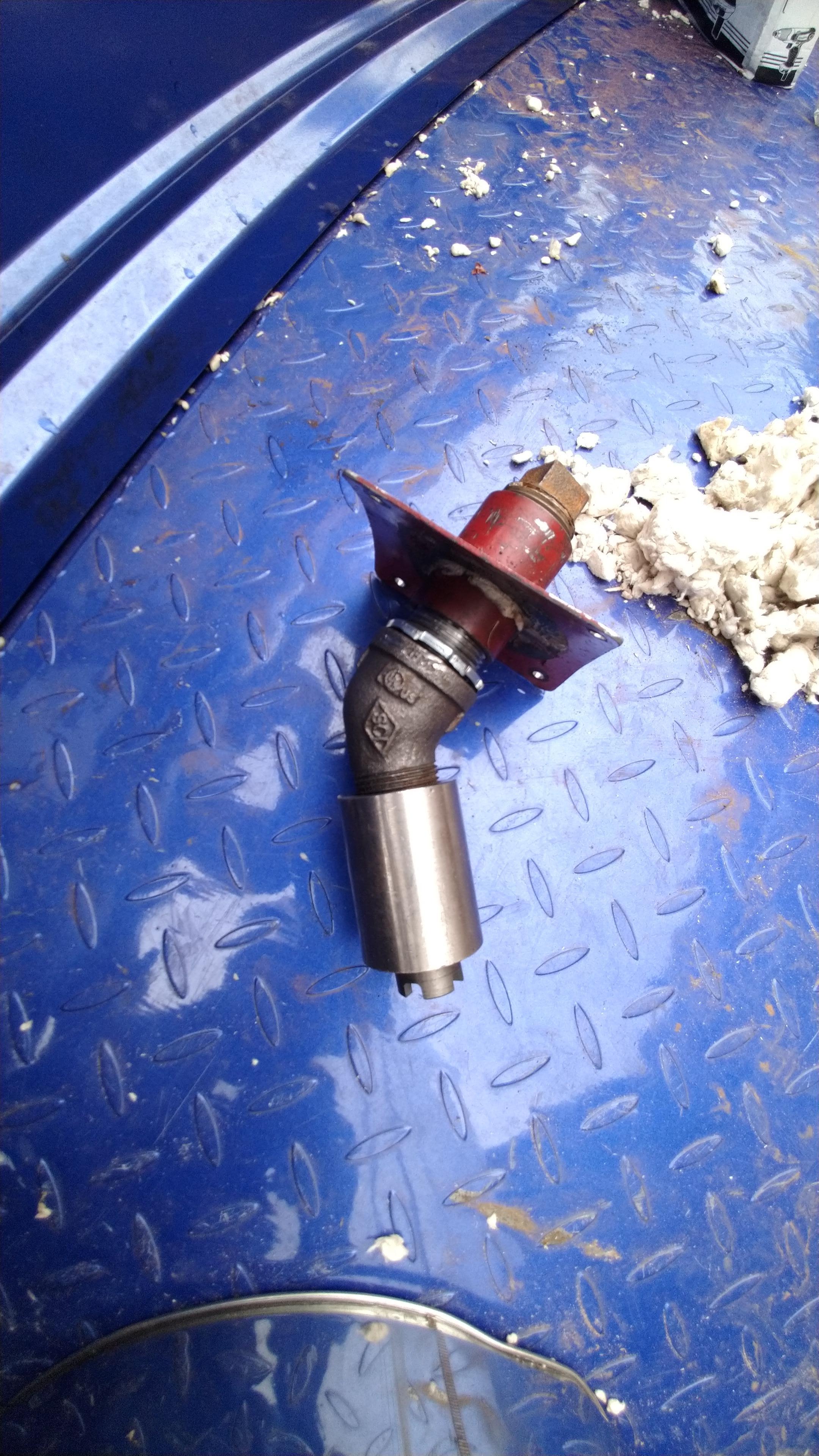
Just back from Rwanda. Here is a picture of our nozzle. Tungsten Carbide sand blast nozzle screwed into a stainless reducer tipped up 45 degrees.
Cargo trike.
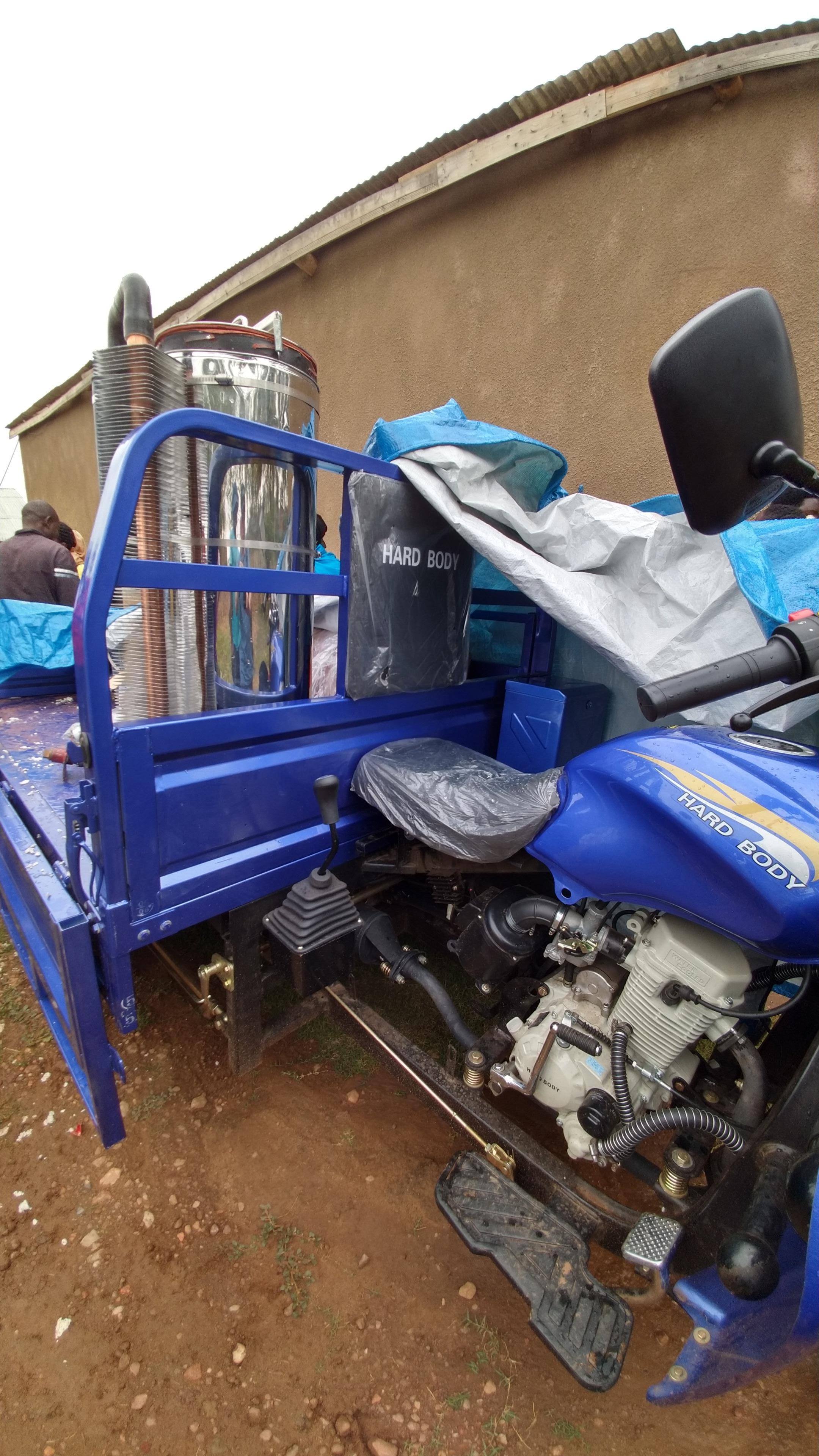
Unfortunately we won’t get to finish this until next February.
8 Likes
Welcome back Bruce , such a shame you will have to wait nearly another year now to get the trike finished and up and running .
I have yet to start running my old system yet due to a very sunny summer so solar has been taking care of my battery charging needs , and i am still hunting down items for building another gasifier to use up those 3 new tungsten nozzles , by the way your nozzles look way longer , where they from the same supplier as the ones i got ?
Dave
1 Like
The tungsten carbide is that little crown-shaped piece on the end. It is the same size that I sent to you. The big piece is a thick stainless steel 1" F to 3/4" F reducer that I picked up somewhere.
1 Like
Ah i see ,Bruce is there a reason behind screwing into stainless steel adapter ? i was just going to screw it directly into the fitting and hope for the best , but i guess it will get the heat away from the iron fitting and give a little extra length into the gasifier
1 Like
I want to use 1 inch pie for my external plumbing, so I needed a reducer for the TC nozzle. I had this massive SS piece in my junk. It just kind of fell together and gave me the right length for my 12 inch diameter reactor. There is a better picture of this setup at post 191 above. I was planning to seal the nozzle threads with high temp ceramic paste, but I don’t know if that is necessary.
I’m looking forward to getting some reports from your winter usage to see if we are on the right track with this. I hope to try this TC nozzle on something this summer, but nobody that I know of gives the kind of real world testing that you do.
4 Likes
Hi Carl:
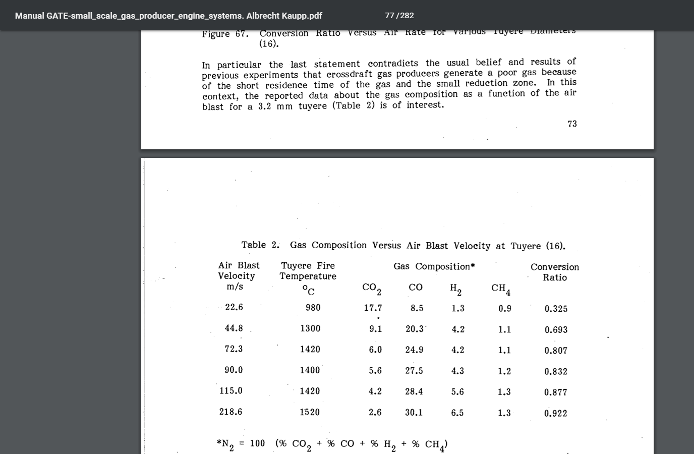
The interesting chart you are referring to is the “Conversion Ratio versus Air rate for various nozzles diameters.” is figure 67 @ page 73. Belongs to: Small scale (20-100 HP) gas producer-Engine systems (Edited 1984). Normally know as G.A.T.E. (German Appropriate Technology Exchange).
Authors: Kaupp/Goss.
The author refers that this info was based on “The Gas producer for motors vehicles”. Institution of engineering, Australia Journal, V14, # 4, 1942, pp 81-93.
The next following picture (table 2 @ page 74) in this same manual is also very interesting, because it give a 3.2 mm diameter Nozzle Temp depending the Air blast velocity (mts/sec).
B.R.
Eddy Ramos (Argentina).
9 Likes
Carl suggested I document my experiences with nozzles in my Toyota Corolla gasifier, particularly to show my results with horizontal air entry versus vertical air entry to the reaction zone of the SimpleFire updraft-style charcoal gasifier.
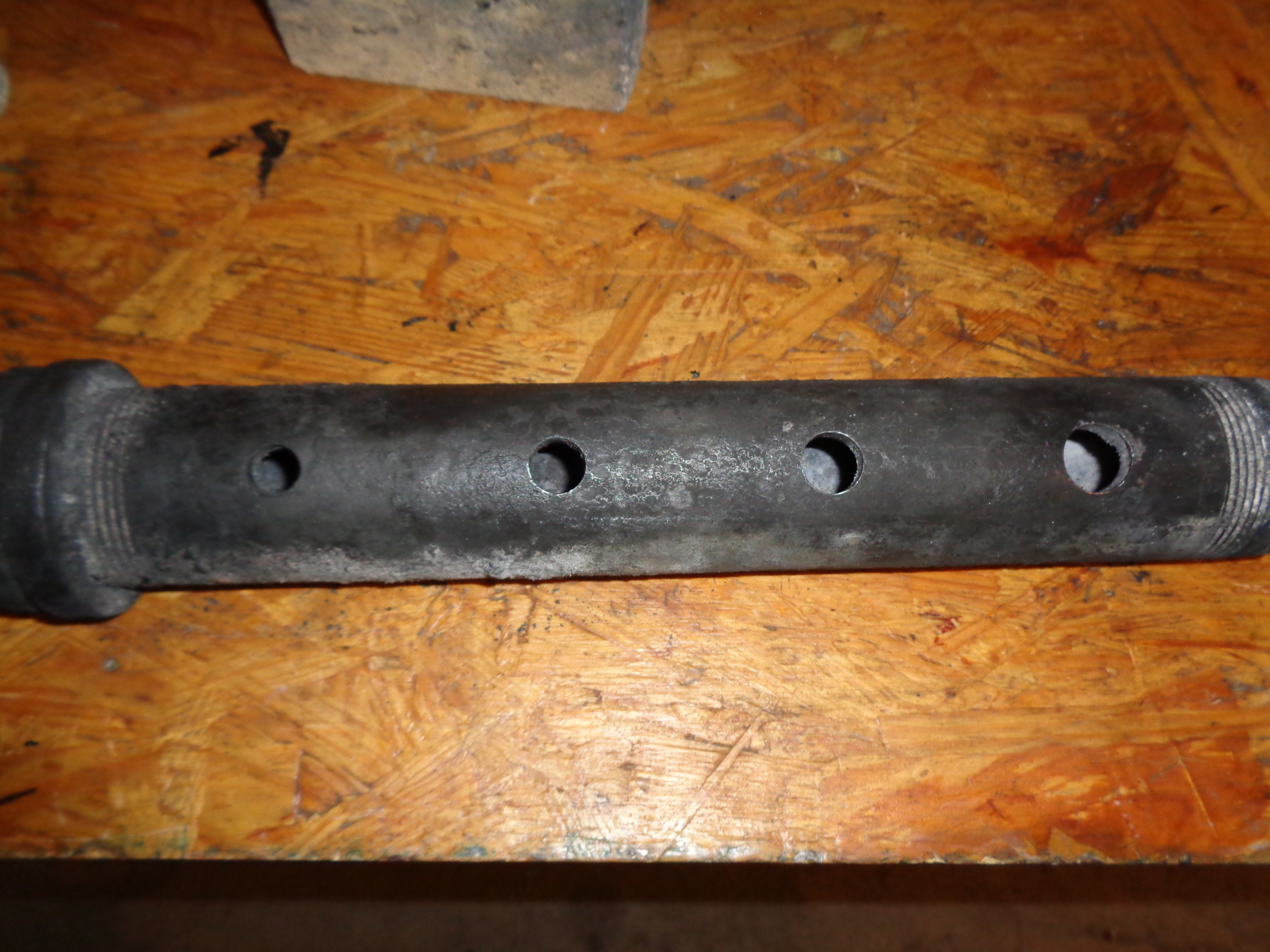
The first photo shows the original side air inlet 1.5 inch stainless steel pipe nipple nozzle with a stainless steel sheet metal shield after about 20 miles. This pipe nipple was mounted horizontally. I replaced that with the Lettinger style nozzle shown in the same photo after it had been used for about 65 miles. This nozzle is made of a 1.5 x 12 inch schedule 80 steel pipe nipple used for steam applications. It screwed in place of the side entry nozzle, but functions as a vertical nozzle with the holes facing up toward the gas outlet at the top of the reactor.
Below is a close-up of the Lettinger nozzle after 65 miles.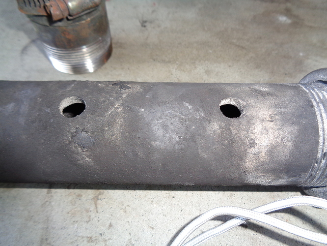
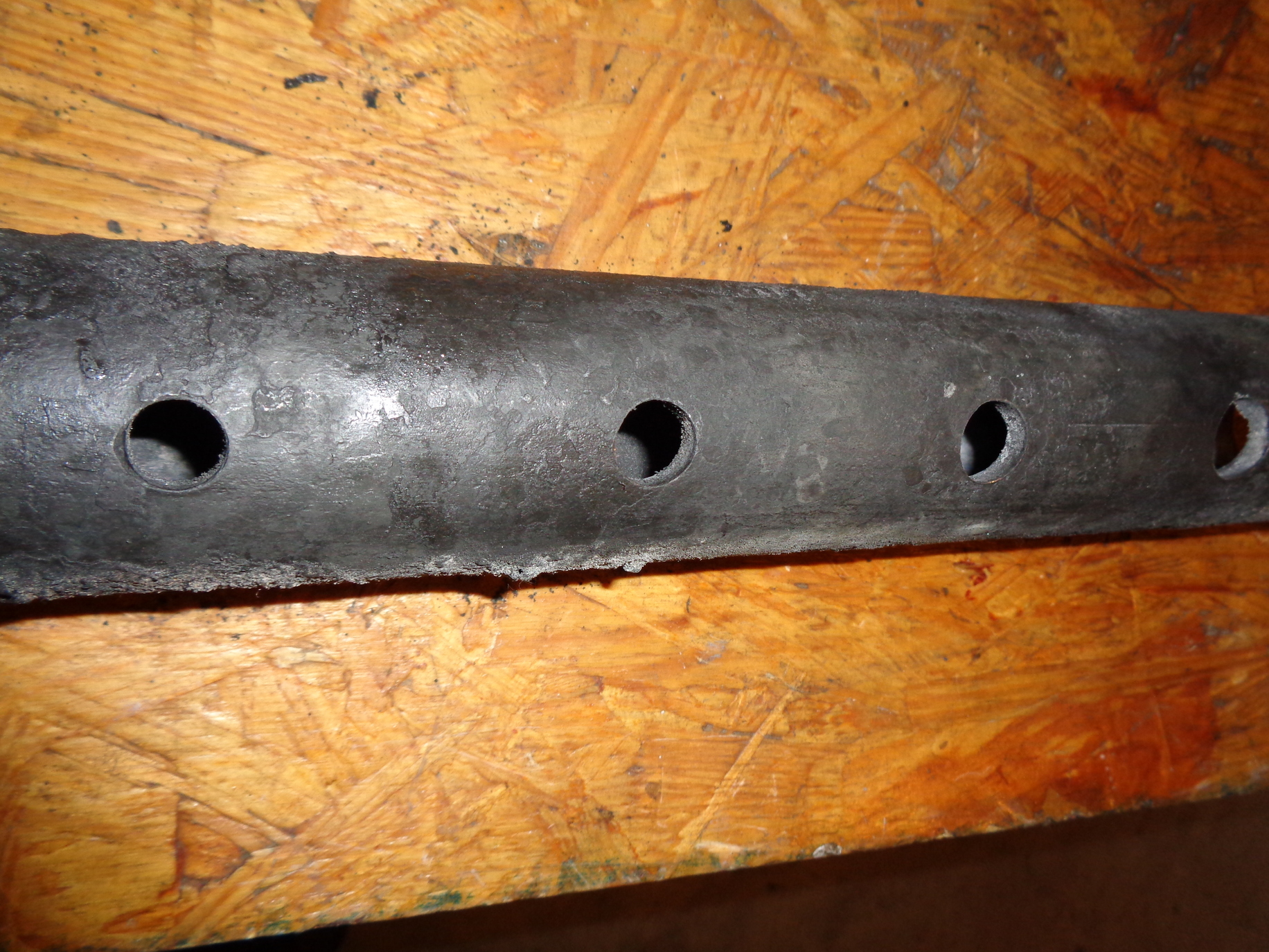
I had the holes drilled larger in the Lettinger nozzle and reinstalled it. Then after 128 more miles this is what it looked like:
I did not notice any deterioration. Here is a close up of it:
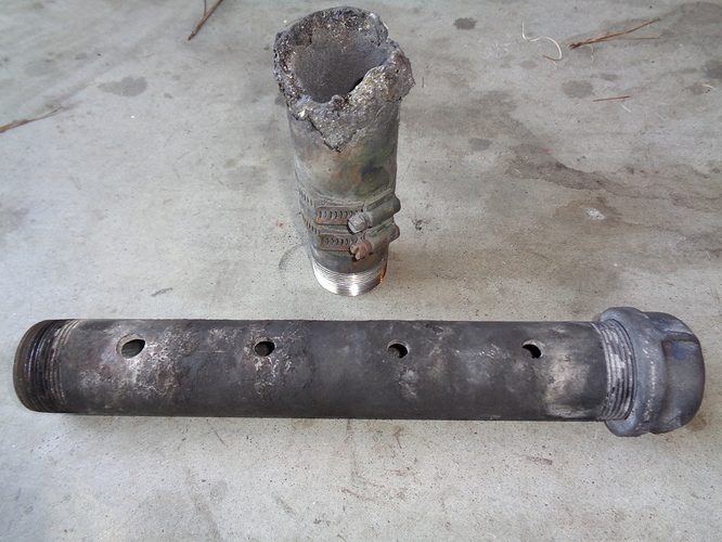
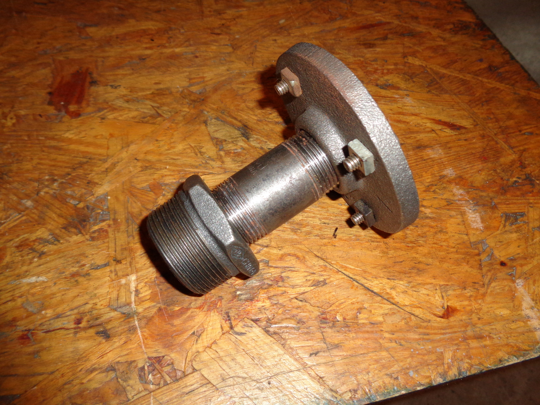
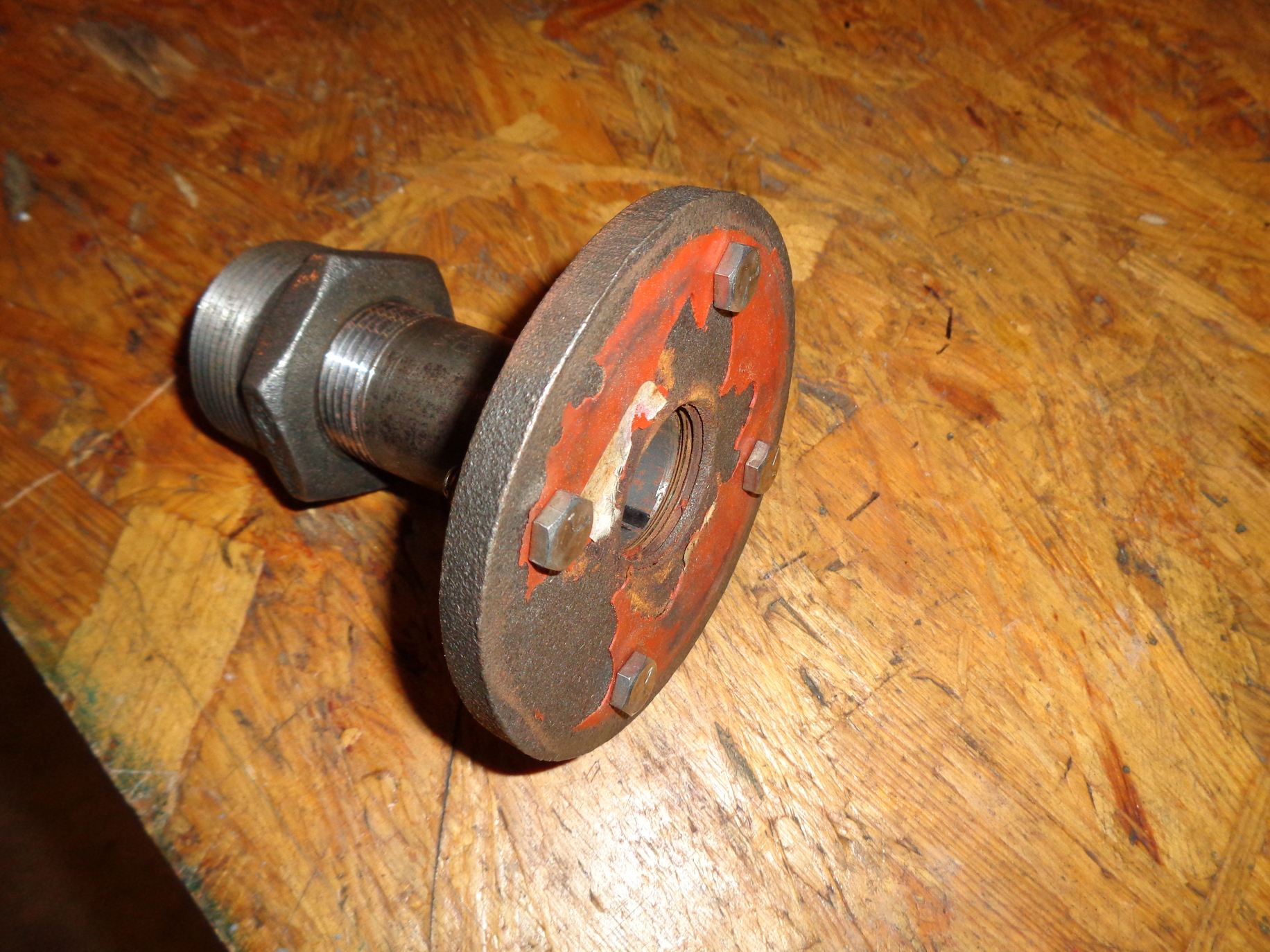
I had the “bright” idea of trying to lower my reaction zone by going back to a side entry nozzle similar to the first one, but with a one inch pipe and a heavy floor flange on the end to protect it. Here are two view of it before installation:
Here are two views of the results after only about 15 miles. The most deteriorated part was facing up toward the gas outlet with an accumulation of slag at the bottom.
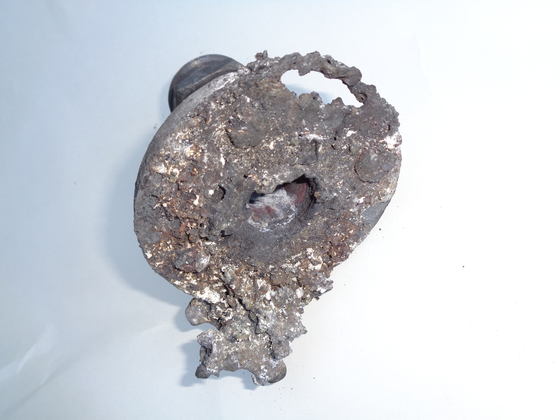
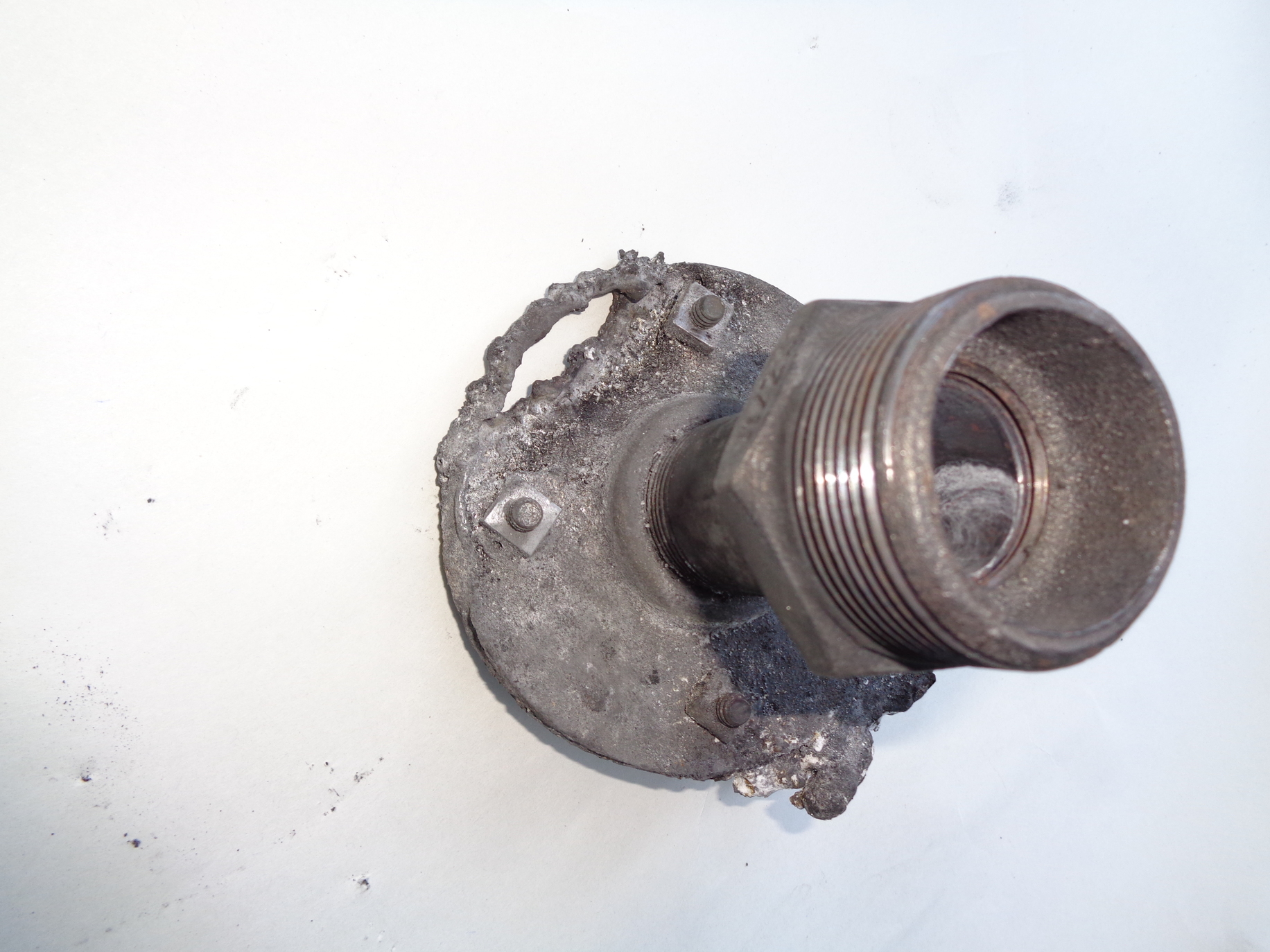
Lesson learned for me: Unless there is some cooling method employed and/or material which can take the high heat, the side entry nozzle is not likely to last long in the updraft gasifier. the nozzle will fare better if the gas is taken off opposite the direction the air is entering the reaction zone. I have decided to stick with Kristijan Lettinger’s design.
Others have pointed out that the durability of Kristijan’s design is due to the mass of metal surrounding the holes and the accumulation of slag on top of the pipe forming a protective coating for the pipe which separates the pipe from the glowing charcoal.
One disadvantage with this nozzle design is that it is difficult to monitor the temperature by the color of the glowing charcoal, because you can’t see it clearly from the air inlet, but as Kristijan has pointed out, by examining the accumulation of slag vs. ash at clean-out time, you can determine whether it has been running too hot or cold and make the necessary adjustments for future operation. If I remember correctly, a lot of slag formation indicates a high heat situation. I remember the first time I removed the Lettinger nozzle, there was virtually no slag. The last time there was nearly an inch of slag formation on top of the nozzle. Hope this helps.
14 Likes