I still can’t follow the check valve idea. It seems to me that all three valves will open partially at the same time instead of sequentially. Don’t they need to open sequentially in order to maintain the optimum superficial velocity at the nozzle?
1 Like
Yes and no… Let me explain…
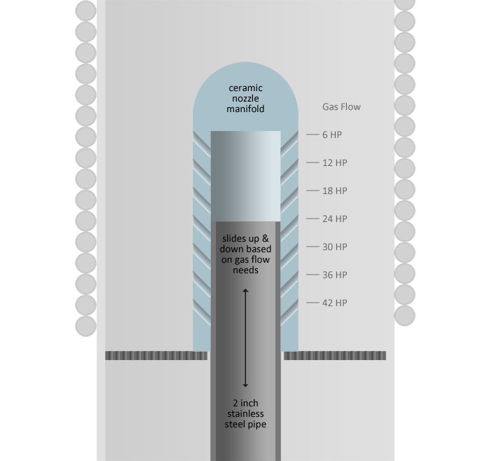
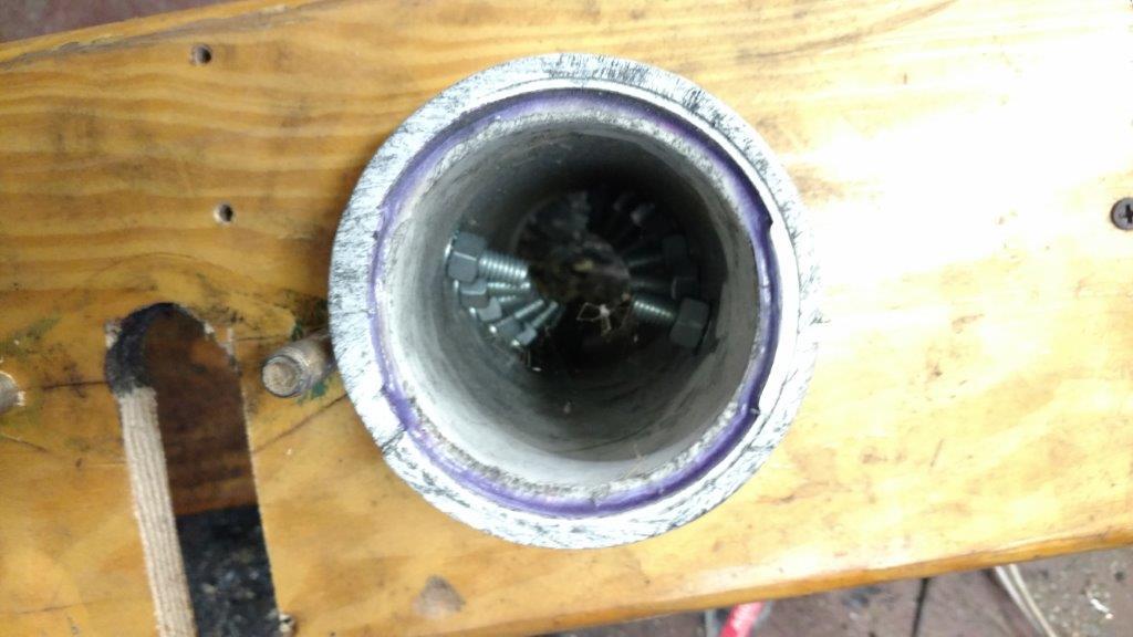
Consider a 3-nozzle system. All nozzles are pointed inward at 120 degree separation, and at a 45 degree angle downward. The core is an ~8-inch ceramic pipe (or lined w/ ceramic blanket). The first nozzle is unchecked, and is the most crucial for air velocity…
The unchecked nozzle—almost by itself—will create a combustion zone temperature ideal for the most potent gas.
That whole core area, because it is within a small cylinder, will be at a high temperature already, so any additional incoming air will be converted to good gas within a few seconds—enough time for the reactive carbon to form at the tip.
The other two nozzles are more about flow rates than temperature. The hotter the temperatures get, the more water we can use to get H2, so we do want a good velocity from those nozzles as well, but they are far less critical than the single, unchecked nozzle.
Note: The chart above was for H2 production, so the H2 levels are more than double than what we’d get, but the temperatures are the same.
So, in short, even if the check valves are opening and closing, inconsistently, because of a border line suction level, they will still serve the overall flow requirements set by the engine.
It’s also why I want to use a ceramic blanket or tube in the core, so that as much heat as possible is reflected back into the middle… less metal fatigue, and more chance for the temperatures to be well above ideal, so we can increase the H20 drip rate (or EGR, oil, etc.)…
This all sounds nitty gritty and far from practical. I understand that most readers here will roll their eyes about this, but I am determined to build an “adjustable flow” gasifier if I can…
The only perfect scenario is to use actuated valves, but I want to try this without the need for electronics on these micro units.
2 Likes
Hi Troy,
worked with these already
did take out the spring, works as a sharm
2 Likes
I had forgotten about that one Koen. The tractor does not need one the atv might work better if it had one I should try that. I will for sure put one in for the small inverter genny if I ever get to it.
David Baillie
Koen and David, It seems this was to mitigate the short bursts of what would be positive pressure from small engine air intake manifold. Is this correct?
I noticed this “pulling and pushing” effect in the past on an old Briggs & Stratton, but didn’t see this effect on our Honda, and kind of forgot about it.
So, we know that the springless vertical check valves will work. How good for nozzles? Still to be determined…
I will be using check valves to try to maintain optimal conditions in the core by using—as Koen put it earlier—vacuum-reacting valves. Here are some earlier concepts from a couple years ago on other DOW posts:
Concept: Koen
Concept: Koen
Concept: Troy
The first concept by Koen—without the springs—is what I’m trying to accomplish, both for the nozzles, and for the mini-cyclones…
1 Like
Troy,
Ahhh, one unchecked valve, but valves on the others that opened with increased load – sounds plausible.
Thanks so much.
1 Like
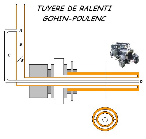
Hi Troy
you know this nozzle has two speeds may be favorable ?
2 Likes
Hand-Crank Mechanisms
I am deeply fascinated in human-powered mechanisms. When I see the old blacksmiths forge blowers, I can’t help but to pay homage to the cleverness of our ancestors. There is something about hand-cranked mechanisms that speak to me—perhaps irrationally—on a different level. I want to reach through my LCD monitor and start cranking away.
I also feel that there is some level of common sense as they relate to this gasifier project. I don’t want to rely on a 12V battery need to power an electronic fan to get the system started. I’d like to keep every aspect of the system as components that remain non-reliant to batteries and electronics. However, I have no problem with electronic devices being used on top of this base (human-powered) layer… in software, this is called “progressive enhancement,” and i think this principle applies in this case—rather brilliantly.
In short, I want a hand-crank blower with a power shaft that could be paired with an electric motor. While we’re at it, let’s take this to another level…
If we are going to have a hand-crank mechanism, shouldn’t that same device be made for use by other purposes as well? Wouldn’t it make sense to have that same gearbox be able to handle charcoal grinding and sifting? Of course it should—albeit with different gearing.
So now, I need to consider a multi-purpose hand-crank mechanism that can be used for starting a blower, crushing charcoal, and to spinning a trommel, but have it be intuitive in its placement and it ergonomic positioning.
Will it be detachable, or will there be some kind of lever that engages and/or disengages with these different systems?
This will be a fun and challenging problem to solve.
Just in case you haven’t gone here already in your thinking:
For a blower we can use an arm-sized version, but for grinding we are probably going to need our legs.
4 Likes
I have a hand cranked charcoal grinder for makeing all the charcoal l neaded for my Seat, fast, simple and effective. Go with simple, it always works best. No real nead for a complex gearing, its much simpler to just adjust the numer of teeth if goeing for a GG style grinder to mach hands rpm and torq.
1 Like
Thanks Kristijan.
Besides my “ab-roller” grinder, I have made three other hand-powered grinders for charcoal. The first had teeth (5/8" X 3/4" studs) on a cylinder that rotated between spinning saw blades.The second used interlaced and counter-rotating saw blades and the other has stationary metal fingers between rotating saw blades. These designs work, but require a lot of back and forth motion to keep things moving through.
Your experience is sending me back to take another look at a hand-cranked grinder. I assumed that the big teeth and fingers on the GG style would be too hard to hand crank.
1 Like
Kristijan & Bruce,
Any chance you could share pictures of your grinders? If they are fast simple and effective, as Kristijan says, I would like to see what they look like, if that is ok with you… Even if they are copies of another design—such as Gary’s—I’d love to see them. Thanks!
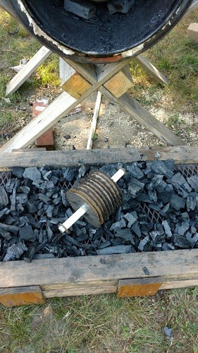
Trigaux, that’s an interesting nozzle… It might not work for the OpenFire because I plan on preheating the air before it hits the air nozzle with braided stainless tubing. I’ll be wrapping the core tube with it in some fashion… Thanks for posting it.
Troy,
I spent last half a hour looking for that picture of the grinder but cant find it anywhere. Imagine a 3" pipe with 8x8x10mm pins welded in rows, the number of pins, and the number of rows (lengh of 3" pipe) determins hand torq required. The stationary anvil dimensions determin charcoal size. Very similar to Garrys grinder. The only difference it has more teeth and its hand cranked.
Ps the positive effect of a hand cranked grinder is you feel what kind of char you are dealing with. Any unchared wood that wuld be crushed in a motorised grinder, you feel on the hand an can eliminate.
1 Like
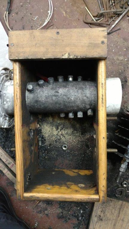
My copy of Gary Gilmore’s grinder is not hard to hand crank. I wear a dust mask, and crank it with the right arm. The hopper holds a plastic bucket of raw charcoal. I grind a couple of buckets, then put it on my 1/8" hardware cloth screen and sift it through with a brush.
http://imgur.com/EaMCZcE
http://imgur.com/DX56lmV
The grinder teeth are made from old railroad spikes. They are welded onto a three inch iron pipe, and that pipe is tack welded to the bicycle crank. Quick and inexpensive to make.
I inspect my raw charcoal before and after it goes into the grinder, mostly looking for nails, bolts, and any small brands.
4 Likes
I love the bicycle mount idea!
Here is a picture of my default charcoal processor:
“Ab roller” made of saw blades with wood spacers on 5/8" bolt with PVC handles. I’m thinking about trying a long handle on this so I can stand up rather than leaning over. 3/4" expanded steel on a 2" X 3" frame over another frame with 1/4" screen. After crunching charcoal through the 3/4, the top frame is lifted off and the 1/4" screen is shaken longwise on glder strips, leaving the frame full of engine ready fuel. Garden biochar falls through to the box below. This is my quickest down and dirty system.
I’ll try to get pictures of the other grinders for you later.
2 Likes

Hand-Cranked Fan Update
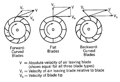
Been doing some research into hand-cranked fans, and I’m pretty sure I have the answers I was seeking… Like everything else in physics, there are gives and takes. The backward curved blades and the radial blades are similar in performance, with an advantage going to the radial blades. It turns out these are also the easiest to manufacture.
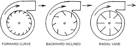
Excerpt from Gingery’s book:
“The forward curved vane type is the familiar quiet “squirrel cage fan” found in low pressure applications. It is made up of many vanes of small area that are curved in the direction of rotation. The wheel will often be about as wide as its diameter, and the inlet opening will often be nearly as large as the wheel diameter. Although it can generate pressures up to 1-1/2” water column, it is most often operated below 1" water column.
Compared to squirrel cage fans, backward inclined vane fans have fewer vanes of greater area that are inclined away from the direction of rotation. This produces a non-overloading characteristic which makes it ideal for commercial heating, air conditioning and ventilating applications where load conditions in complex duct systems vary greatly with time. These fans must run at higher speeds to do the same work as the forward curved types resulting in noisier operation. Although capable of higher pressures, backward inclined vane fans are not usually operated above 3" water column of pressure.
The radial vane type is characterized by straight vanes of greater depth with the wheel usually being narrow in proportion to its diameter. It is capable of pressures well above 12" water column and very high velocity. Radial vane fans are usually of much heavier and stronger construction than ordinary ventilating fans, and are much noisier. This type is most often needed in shop applications. This is the basic design type discussed in this manual since it is ideal for exhausting, for conveying dust and dirt, and for forced draft applications.
The number of blades, or vanes, in a wheel has an effect on performance and efficiency. Low pressure, high volume fans will have many blades while a high pressure radial vane fan will have fewer. In general, increasing the number of blades will reduce slippage and thus increase efficiency until a point is reached where losses due to friction and reduced inlet area will offset gains. A commercially built radial vane fan might have from 5 to 12 blades while a backward inclined wheel might have from 10 to 20 blades. A curved vane squirrel cage fan might have from 30 to 60 or more vanes. Since multiples of four are easy to layout with available home shop methods, I have found that 8 blades works well for most high pressure fans, while 16 blades do nicely for higher volume needs when pressure is not the main requirement."
4 Likes
Seems like a pedel bike would better than a hand crank fan, just hook fan in place of back tire.Nice info on the fan types and there diferences,though i caint read as fast as you can write.
1 Like