So the machine is back together and running on gasoline. I tared this thing up pretty good, I had to go in and free up the valves. It was suggested to me at Argos to heat the valve. Ive tried this long ago and stopped as I was getting too much heat wrecking the valve seals and distorting the spring. I thought I would revisit this but use very mild heat and I thought it worked. Did not see any ill effects from it.
(Never ever apply heat to your valves even a small amount of over heating will distort your valve springs; I found this out later in tear down. )
So I had the valves functioning again and moved on to attempting running on gasoline. It would not fire other than backfiring. Started to think bent valve, so got the compression tester out and nothing!! No compression!!
So ordered new valves and a re seal kit. Tore into this thing and popped the heads off and valves look fine!!?? Pulled all the valves revealing the distorted valve spring and cleaned everything up. I re shaped the spring same way it was distorted replaced the intake valves and put it all back together. Then I noticed something. the rocker arms were not fully relieving keeping both valves open during a combustion stroke. Yeah that would cause no compression. All four lifters were doing this. Drained oil cleaned out the lifter bores and filled her up with Kerosene. Hand cranked here for a bit and drained and then fresh oil in. Problem is gone.
So the plan is to run on gasoline a bit longer and try to clean it out a some more. While its performing this run Ill fabricate the tar sensor and get it installed So hopefully Ill be back up and running on woodgas by end of day and Ill try to get a video of the sensor readings running in action.
Now THAT could be a game changer. A forced air, natural gas fired home heating system could reasonably produce all the electricity it needs. It wouldn’t have to be connected to mains power at all. It would still continue to function in a power outage. This type of system has been around for a while now but it has been prohibitively expensive.
Rindert
I have all the parts to build a small prototype. This will be my weekend project, hope to have that on video by end of weekend
Alfred, has come back with wanting a 1000 bucks to work with him and wont give me a straight answer on cost for some straight up modules. Very frustrating, I just want cost for the best off the shelf modules he has to offer.
May just have to look deeper for Chinese made modules I guess. But like Bruce has stated the peltier modules are not the same as a TEG. The TEG I do think are a bit more expensive and I have not found a source for them yet.
Yeah Im digging deaper into this as Ive kinda given up on Alfred. Yeah those Peltier modules I ordered are probably only going to put out just a few watts. Like under 10 watts!! each lol.
Yeah the TEG modules are very expensive and some of the best Ive found so far only put out around 20 watts at a cost of at least 50 bucks. So yeah its all coming back and why I never really pursued the technology. However I am still very intrigued and will continue on with this project and sourcing modules that will meet the development goal of a 2500 watt gross / 1500 watt net output unit.
Last night I ran for three hours with the sensor installed. During this entire run I never notice the sensor read out change the entire time. So it either did not work or the machine was simply not making any tar.
Im sitll having flow issues more on that later. But today I went out and fired it up. Crossing fingers when starting the engine and it came to life. YES!! Ok so that still does not mean it works. So as the engine was warming up I notice the read out register and it pulled all the way down from 10 to 1. It then ran a range of numbers bouncing around from 2 to 6. So yeah at this point Im excited and want to get my camera but another part of me like SHUT IT DOWN! SHUT IT DOWN!!. So I ran in to get my camera and by the time I get back out there it has self corrected and it never registered again the rest of the run.
So if I had the code wrote to fault out; this event would have faulted it out and it happened very fast so Im sure no harm would have been done.
So flow issues, I knew I should have ran the 2 inch reductions but I only knew what worked and that was the 1.5 inch used on the Predator 8750. So next week, I will be tearing down and replacing the hearth with the larger restriction. I think it needs less air as well.
Took the weekend off from the build and worked on some experimental TEG / SOFC tech. Ive searched and searched for cost effective TEG’s and can seem to get anywhere and same goes for the Solid Oxide Cells. So time to take matters into my own hands
So I built a printable cell and all of you can do this your selfs if you want to experiment with this. What you need:
Ceramic Cloth / Welding blanket
Carpenter Pencil
Aluminum Oxide / AKA media blast (you can get this at Harbor Freight)
Some sand paper
Sodium Silicate ( binder)
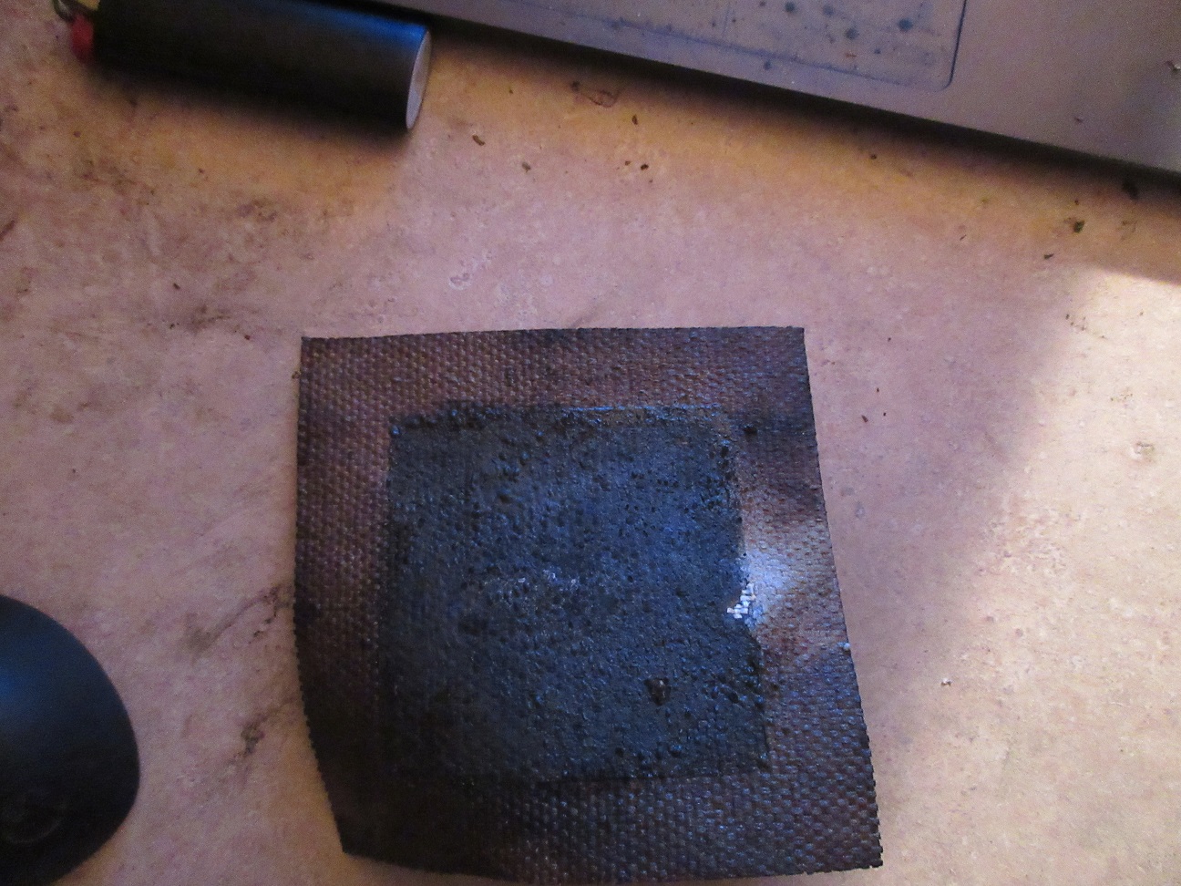
I cut a piece of the ceramic cloth about 5 inches square to create the sub straight. Then tape off a 1" border.
To apply the Cathode side I grind up the pencil lead on a piece of 360 grit (its what I had) 220 would work just as well). I make about a 1//2 teaspoon of the ground graphite. I then add about an equal amount of the sodium silicate and mix well. Then you simply paint this on to the cloth. You want to make sure it is penetrated into the cloth.
For the Anode side you do the same thing however the Aluminum Oxide is already in powder form. Simply add an equal share of the sodium silicate and mix and apply.
Now remove the tape and then apply the sodium silicate around the border of the reactive materials. Then cut off access to make a nice square pallet.
The idea of having the excess and doing it this way is so you can make a metal frame for both sides of cell. This is the part I have not gotten too. The opening of the metal frame will be slightly smaller than the reactive material, this is so you have a good connection all the way around the material. However these frames can not have contact from one side to the other only through the reactive materials.
So this cell is not only reactive to heat but it is also reactive to gas direct from the gasifier. Unfortunately the gasifier crashed and I was not able to make combustible gas shortly after light up. There was a problem with the hopper agitator after the last run so it bridged and burned out. However initially after it first lit it was pretty apparent something was happening as the voltage climbed up very rapidly. It climbed up to around 500 milliamps. I think it would have kept climbing if the gas would have came in.
For this initial testing I simply clamped some aluminum to each side of the cell using some vice grips with a cardboard insulator on the jaws of the grips. I need to make the frame and I bet Ill get a much better connection. Anyways using a torch with the tip about 12" away I can get nearly a 1 volt reading.
So this has been a very fascinating experiment so far. But creating voltage is one thing now to find out if there are any available amps it can offer out. If so than this could hold great promise as this method could allow for these cells to be printed out on a CNC for pennies. This fire blanket I used I dont think is actual ceramic either. I think if actual ceramic cloth was used there is then the possibility of not only printing the cells onto the cloth but then it could be mold directly into functional parts.
Matt for me, you are on the future of the gasifier with loot sofc, in the future this type of process will be the salute of the gasifier, and again, we see the importance of the use of ceramics, the most difficult is the control of the variation of temperature, and especially not to have sulfur and the least possible of CH4 in the SYNGAS, but the SOFC stack accepts the CO and perfectly the H2, but after reaching a certain temperature, Matt , roof alone, you do the work of a laboratory team.
I think you are right, the woven material looks like fiberglass welding blanket, probably won’t handle higher temps.
But the initial results are encouraging. As you say, the detail will be how much current.
Francois has a significant point, sulfur and methane will be trouble. This leads me to think a charcoal gasifier with water drip / added to the charcoal will be the best to feed fuel cells.
I do believe fuel cells will be the holy grail of fuel efficiency. If it can be done practically. It would be equivalent to jumping from a steam engine to a solar panel.
Really interesting work. Fuel cells that can use gasifier products directly would be a huge step forward. Fuel cells can produce electricity at much higher efficiency than a combustion engine, especially small ones like you’d use for off grid applications. Fuel cells obviously also no/few moving parts and that might make for a longer lived, more robust generator.
In my research two types appear to be suitable: (1) solid oxide and (2) molten carbonate, both of which can “reform” the raw wood gas.
Both also have some materials that are yet unsolved. Solid oxide fuel cells are difficult to seal and maintain through the extreme temperature swings they see. The temperatures are lower for molten carbonate but still high enough that the acidic electrolyte corrodes the system quickly. Your idea of using powder on a flexible substrate for the SOFC is really interesting and voltage produced is really promising!
I have some actual ceramic cloth along with some graphine somewhere. I think that stuff maybe in a store n lock. There is also some carbon fiber weave.
I think the sodium silicate is acting in someway as an electrolyte. It may loose those properties after it fully cures I dont know. But this cell was acting like a solid state battery as well. It was holding voltage and leaking down. I think next steps are to find that cloth and dope the sodium silicate with some sort of electrolyte, then pretreat the cloth before adding the reactive materials. The question is what would work as a dry electrolyte doped in the binder?
There are ways to remove the sulfur and there are sulfur tolerant cells out now. We will deal with that when we get further. Just a challenge to overcome. Maybe we will just get lucky and the cells will already be tolerant. Yes steam reforming along with oxygen enrichment are part of this plan. The Oxygen enrichment will slow the gas flows giving it more dwell time in the cells for process. The char unit lower along with the wood reactor will both have steam reforming process to boost H2 yields. Any left over gas will then be redirected back the gasifier combustion process. The water produced from the cell will be used for steam reforming
I spent the day tinkering some more with this. Couldnt sleep last night thinking about this all night. lol
First cell of the day I added white ash to the sodium silicate for an electrolyte. Then this time I hooked it up to a battery and low and behold you can charge it. I was even able to light an LED briefly. The minimum voltage required to light up an LED is 1.8 volts. I was able to light one up at and keep it lit down to around 1.5 volts. So I now know it is capable of outputting usable amperage. This particular one I was able to bring its voltage as high as 2.5 volts charging from a battery. If I let it drop down below 1 volt I was then able to heat it up with the torch and get the voltage up to 1.4 volts. So I broke it in half to attempt to make a series cell in an attempt to get it to light the LED on its own with out charging first. Unfortunately I think I messed it up by cutting it in half.
I then built three or four more but I was not able to achieve the performance of the first one. Not sure why, I think I may have been adding too much ash for the electrolyte on the later ones.
I went ahead and ordered the high temp cloth. I am mistaken on the cloth I thought i had. It is actually silica fabric. This stuff is capable of 1800f and there is a higher temp version. I ordered the thinner sheet size this time as well.
I need to get back to work on the machine, so Ill probably tinker with this at night. Ill build a few with and with out the electrolyte and see if there are any differences. Something that is interesting is unlike a TEG this does not seem to need the cathode side to be cooled. It actually seems to have negative effect. It is starting to look like this is a Thermometric battery?
You are on to something here Matt. A lot of things that have been discovered have been hiding right in fount of our noses sort of speak. I think a lot of people in the pass have been bought out of what they know, by big money people. I commend you for showing your knowledge on a open forum like DOW. You will be Blessed for this.
Bob
I’m curious if it’s made bigger, will it have more capacity for more power or more storage? Also how many times can it be charged. If I know you, you will not rest until you find out the limits of this discovery. Good job Matt.
Way ahead of ya!! lol. Im trying to build a stack and less crude. This first attempt I think I may have some shorting between cells. It is a stack of 6 cells Im only seeing around 6 volts after a quick charge the battery. I think it should be a bit higher than this and should be able to light an LED fully lit even at mild heat.
Right now I have it in a frying pan running around 250*f and only barely lighting the LED. So not so good, but it is sustaining. I think I need to rebuild and make sure there is nothing touching between cells between any active materials and re test. Bit of a learning curve trying to figure out how to build them. Im using a stacked method with end plates that clamp the cells together.