Im running cycle test tonight. Both cell stacks did degrade in performance. I think the sodium silicate before it is fully cured has something to do with the higher performance. I had some issues with the cells getting crushed in the stack as well. This is due to lack of patience lol. I think I need to design a process to make the cells where they can cure with a flat surface.
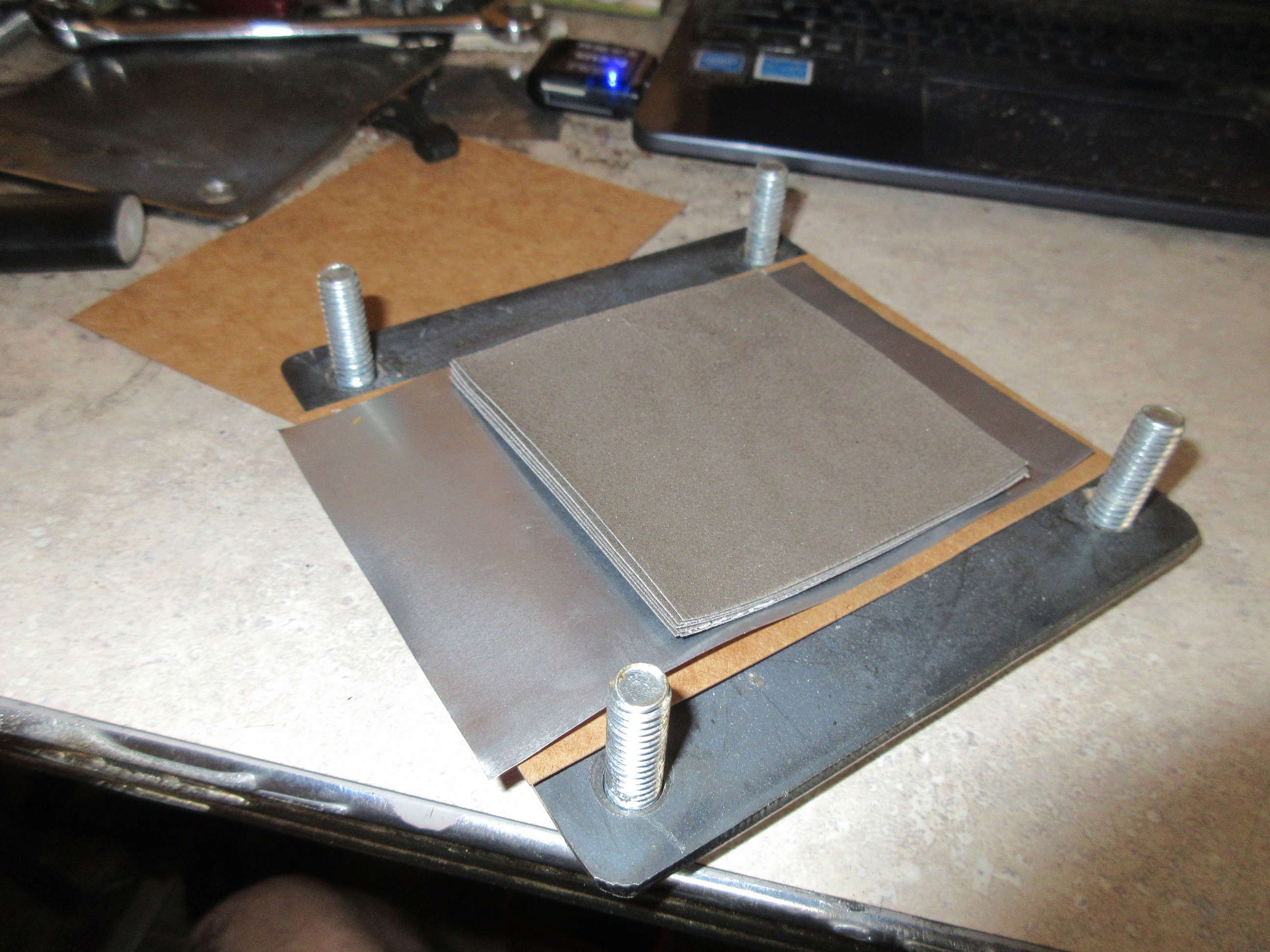
Right now I have three cells stacked in series in a stove pan. I took the last cell stack apart and tested all the cells and only three of the six were good. This makes sense as the stack was just able to light the LED at around 1.6 volts (loaded) and then it dropped off, I think if I had three more good cells it would run the LED. So the three good ones are just stacked freely in the frying pan with a steel blocks on top to weight the stack down. Im running cycles bringing them up to around 500*f and getting 1.2 volts (no load). So thats about 400 milivolts per cell. When this is loaded it really pulls this down. TEG’s actually are the same way. So I think a cell that is fully cured and cycled will need at least 8 to 10 cells to successfully light an LED. At least in this size. If I build with a larger foot print then I think the cells will have better amperage and less voltage drop. Once I find this and can stack the cells in series, I can build bigger. I may also be able to use plain ol paper. If crushed in a stack air cant get to it so it should not be able to degrade. So If I can make it thin. Those little amps each paper cell produces will add up.
Based on the earlier test; the surface area required to light and sustain the LED is about 1/4 the size of a typical sheet of printer paper. I was averaging about 1.6 volts and Id estimate the amp draw around 0.05 milliamps. So roughly 0.32 watts = 1.28 watts pr sheet of paper. Now imagine a typical package of printer paper (500) Sheets. This should then come to 640 watts in a device the size of a package of printer paper. With the right process, this could be done very cheap. Get the paper on a roll and feed it through a laminating process. However, the layers do need a separator. So this will add some thickness. But 0.005 sheet would work or even thinner. But unlike a TEG where one side needed to be heated and the other cooled, this only requires to be heated. So we could build a large stack, eventually the entire mass will absorb the heat. It will just have a bit of a start up time. I think I could potentially cram 2500 watts onto a system cost effectively. All the machine would have to do is maintain 400 to 500*f temp of all devices. So to put into perspective we are looking at 4 packs of 500 sheets of paper but with an added aluminum sheet. So about twice this size assembled.
This is all theoretical at this point, but its also the very beginning stages. Either it wont work or it will get better. I do plan to use Graphine and this should have an impact on the energy density pr cell surface area.
A TEG uses the gradient temperature from both sides. That’s why in some cases they use water to cool the opposing side that heat is applied. Are you thinking this setup does not need a hot side and a cold side?
I came to a conclusion today that what I think this actually is; is a DCFC. After the cells degrade I noticed the graphite side seem to deplete. In my previous post where I thought I was crushing the cells, this was not the issue, the carbon was depleted on those cells and then limited the circuit for the entire cell stack.
Great information Francois. It appears this technology is taken quite seriously, and has already been fairly developed. Apparently 200Kw demonstration plants have been operated, and the intemt is now to deploy a 50Mw demonstration plant by 2025? I see their last charted goal is to utilize syngas at scale.
If this technology can be employed at small scale, for electric power generation, and particularly electric vehicle range extension, it could change our world.
Though in view of the record temperatures throughout Europe and the arctic, and the hottest June ever seen globally, I fear nothing will save our planet or civilization now.
I talked to a patent attorney last night and for United State patents there is a one year grace period. So Im going to ahead and disclose what i have uncovered.
Turns out it is the sodium silicate that is reacting with the heat. This is currently being investigated as a solid state electrolyte for new battery technologies. On my previous cells the architecture was not factoring in the sodium silicate as the actual electrolyte is was used simply for a binder. I think there was some direct shorting on earlier cells causing the degradation.
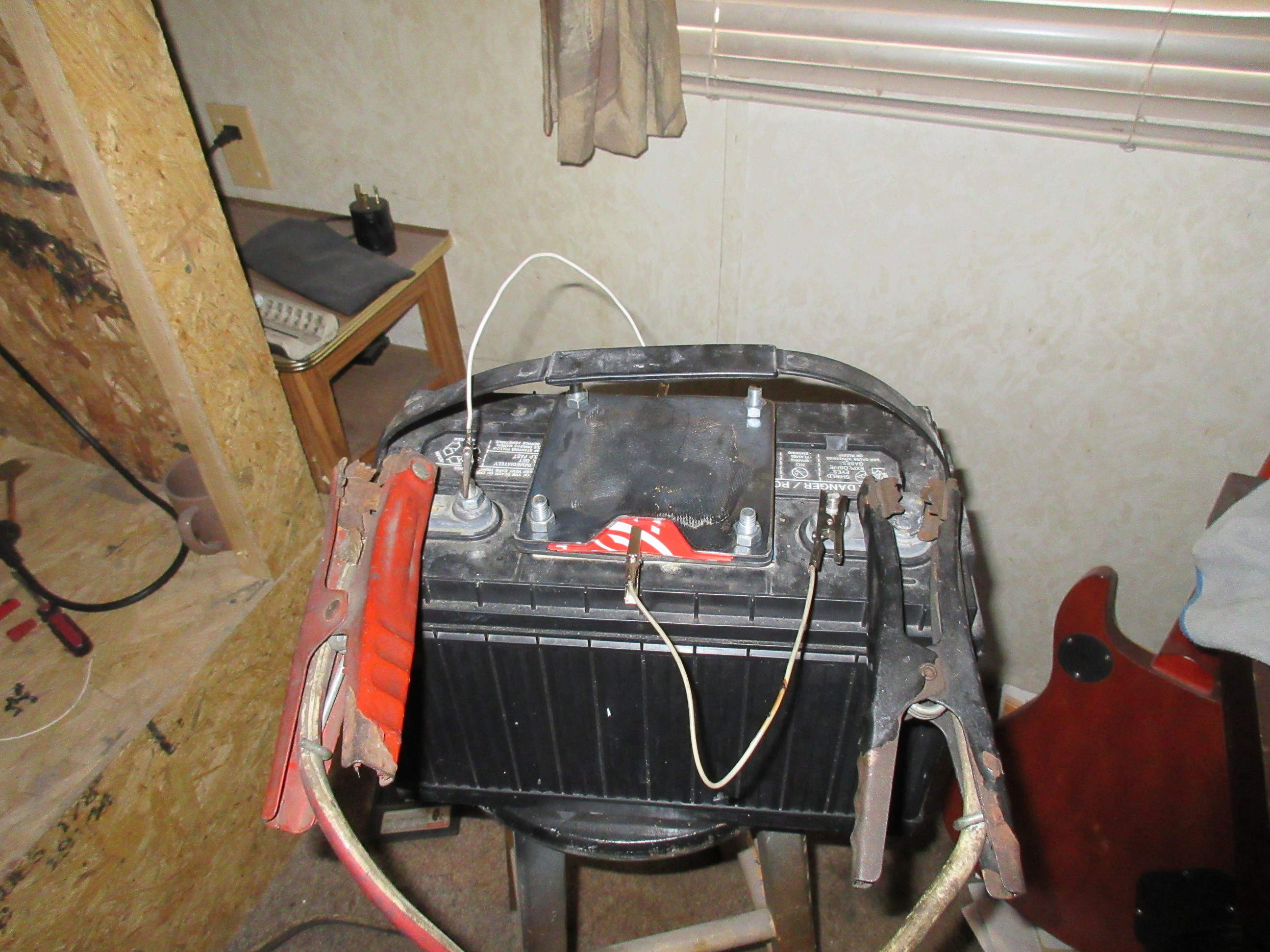
I built a very crude cell and ran it for around 12 hours. You can charge these cells directly from heat or they can be charged directly from another power source. This could potentially be huge as this would eliminate any charging devices charge directly from heat. Coupled to wind or solar that power could be directed to the cells and then at night the stove apparatus would maintain that charge over night.
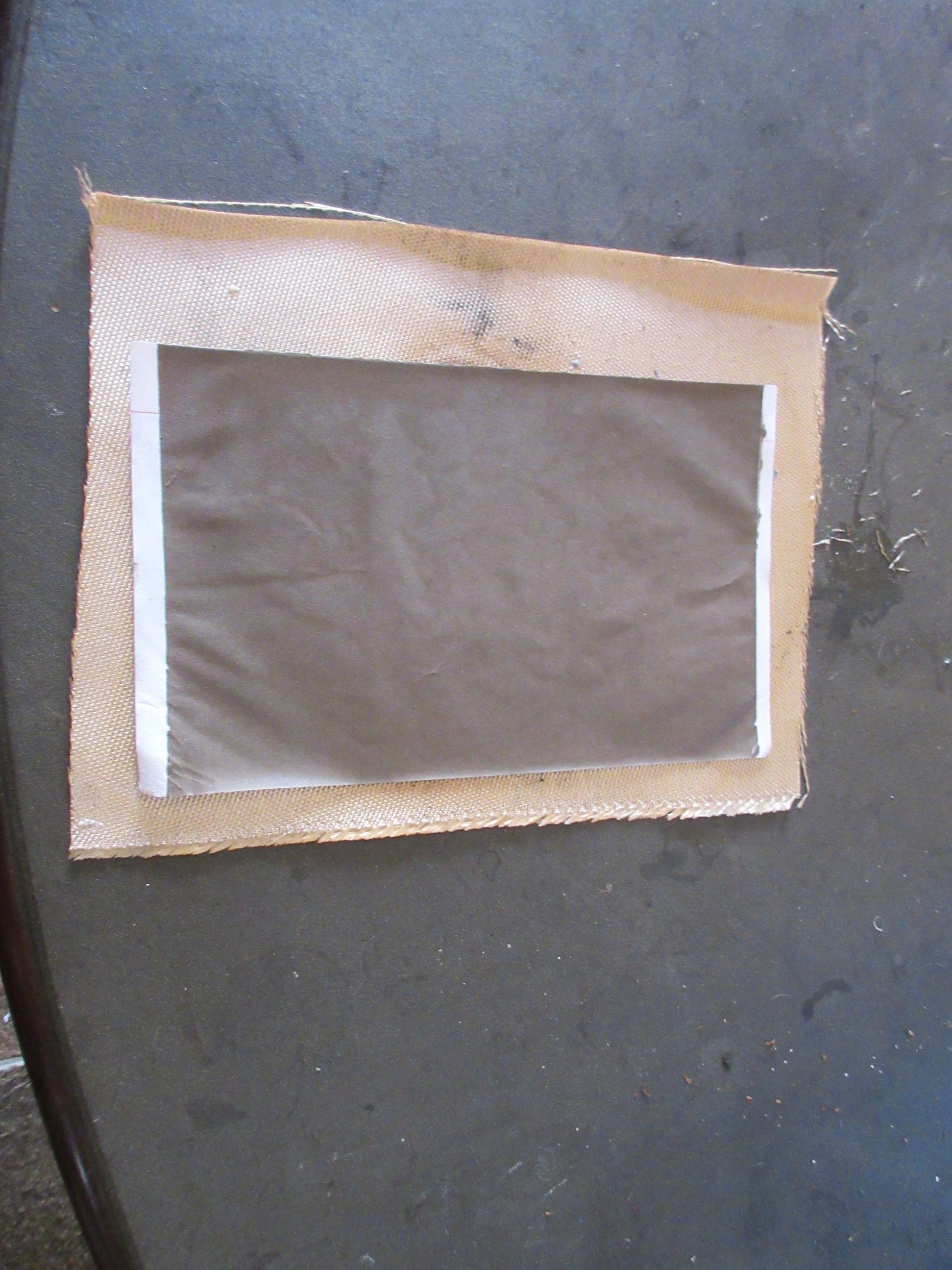
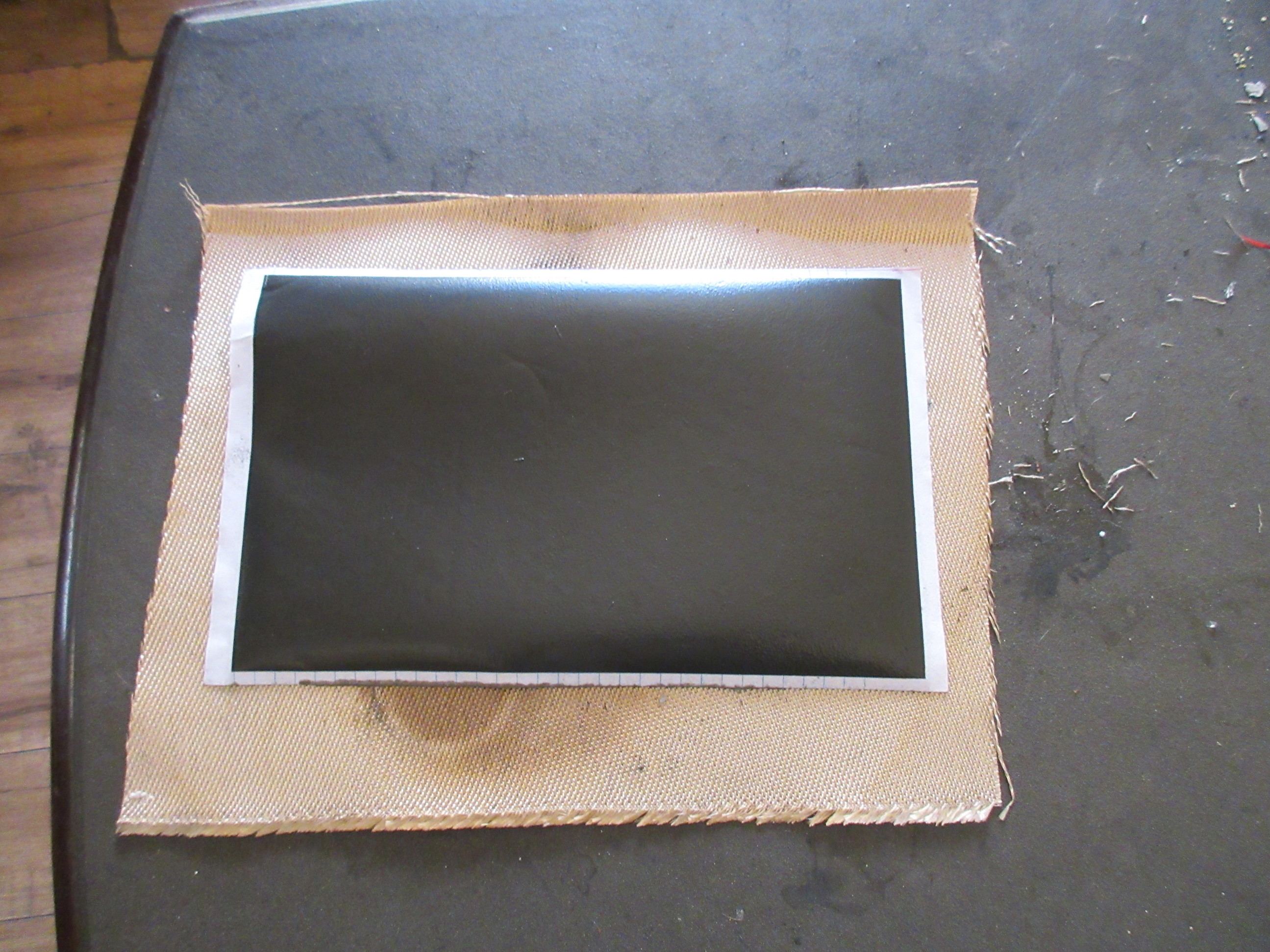
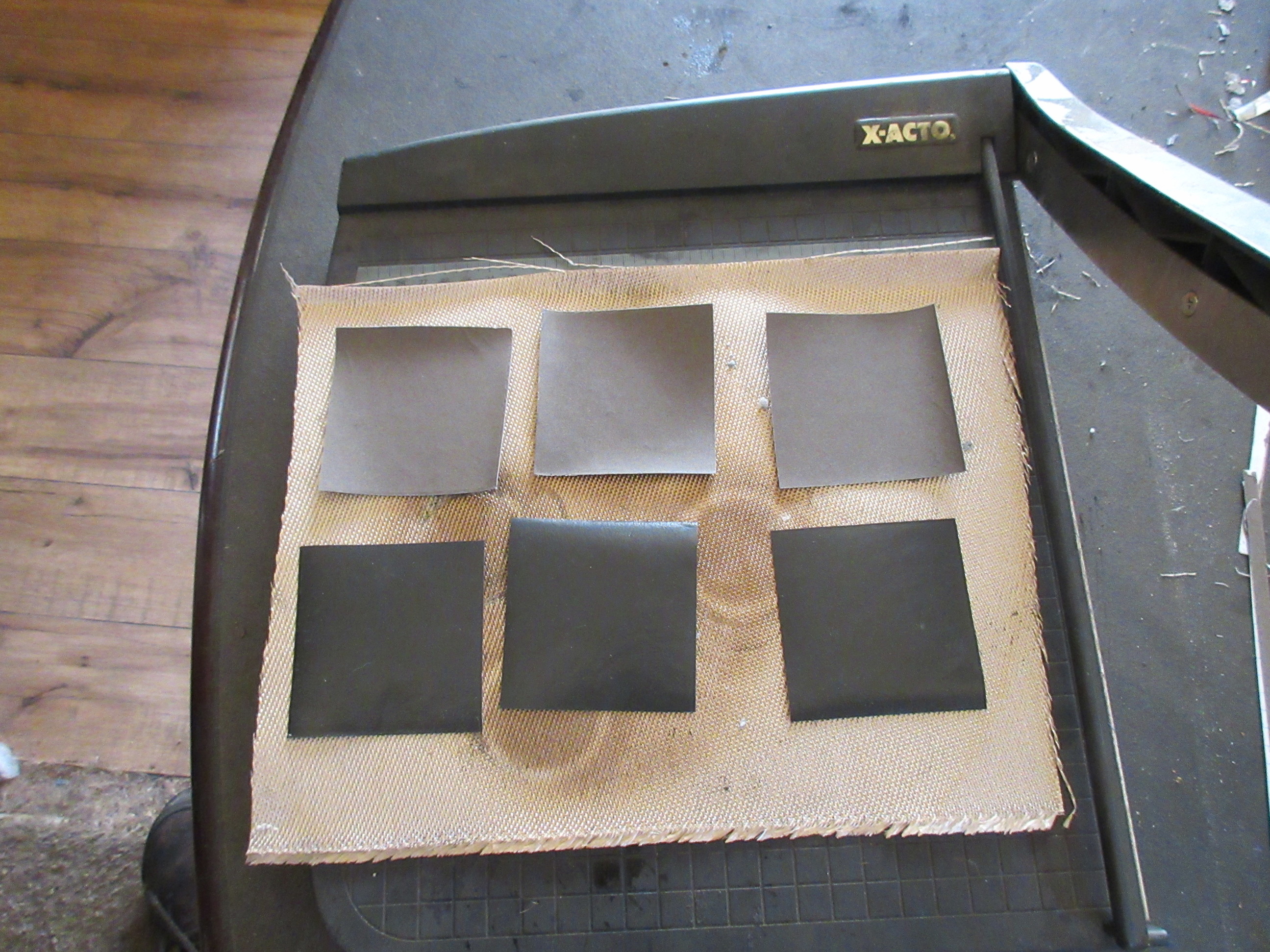
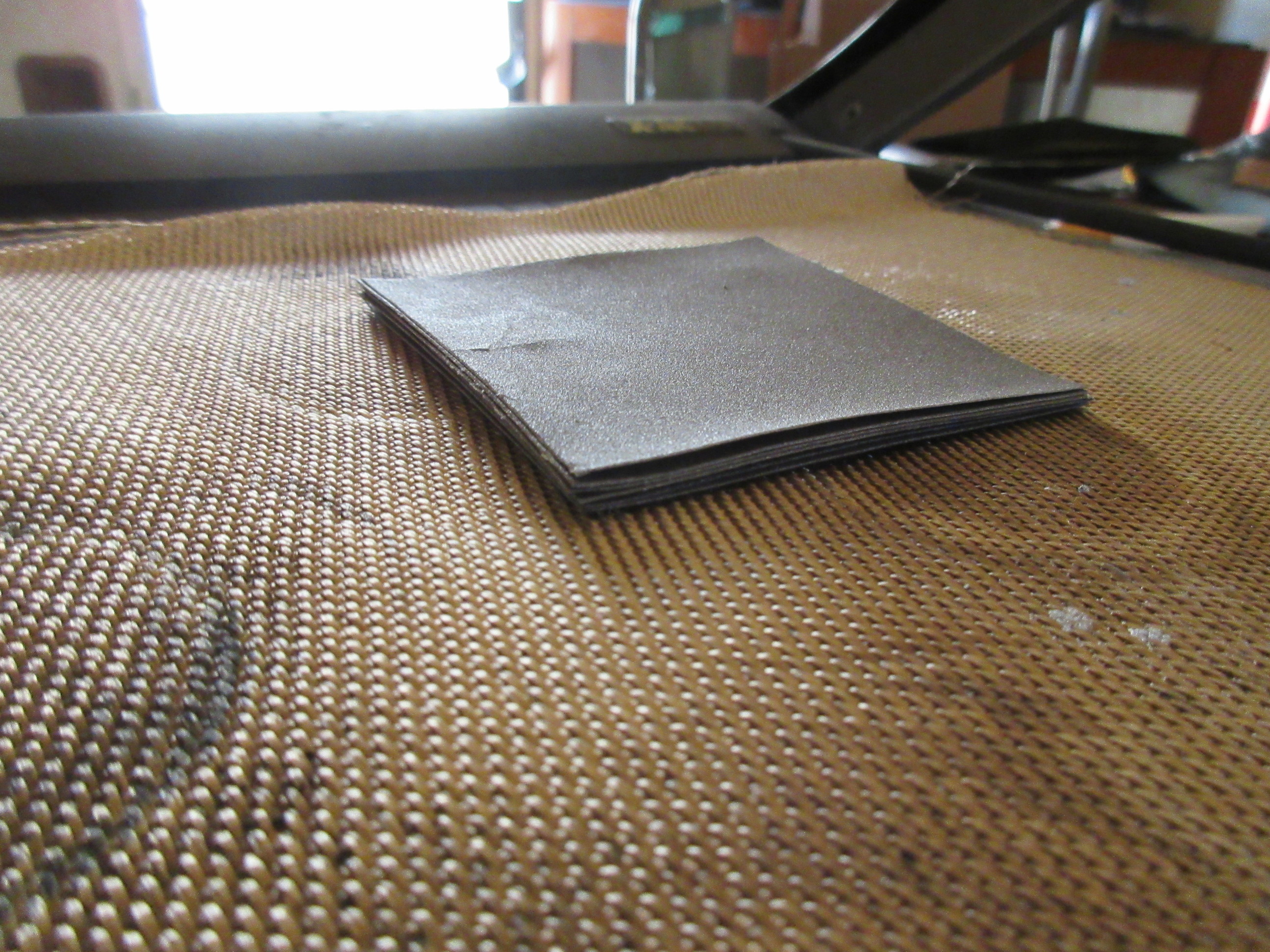
So this is ordinary note book paper. I coated both sides with straight sodium silicate and let dry. Then coated one side with a mix of sodium silicate / aluminum oxide. Then the other with a mix of sodium silicate graphite. Then it up into 3" X 3" cells for a total of 6 cells in this stack.
Now there may be better chemistry to make this work. cobalt oxide I believe is what is used in Lipo cells. So I may investigate this as a replacement for the aluminum oxide. Graphine will come later once I have funds to purchase it.
Right now I have this cell stack charging for one hour and then Ill put it to the test. This is only the start I believe this is going to get much better
I am playing catch up again. But I was poking around looking at the Dasifier, and trying to figure out what Das Agua was doing with his gasifier because the drawing someone made, and the video don’t jive. I know I have done this before like 10 years ago. I re-ran across Das and Tom Reed’s patent to improve hydrogen production from a gasifier which you may have already seen, but I will repost it anyway because they are claiming like 40% hydrogen.:
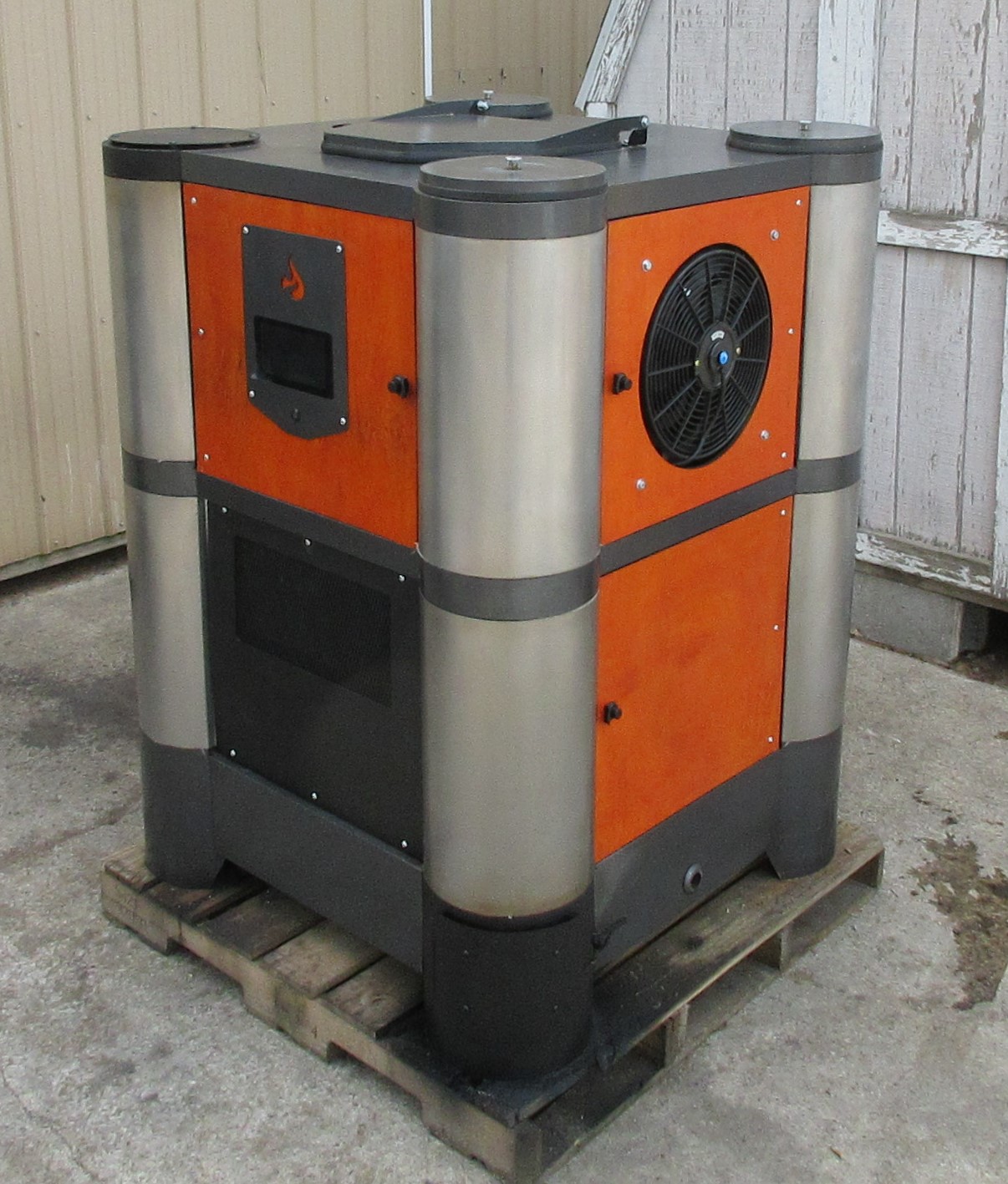
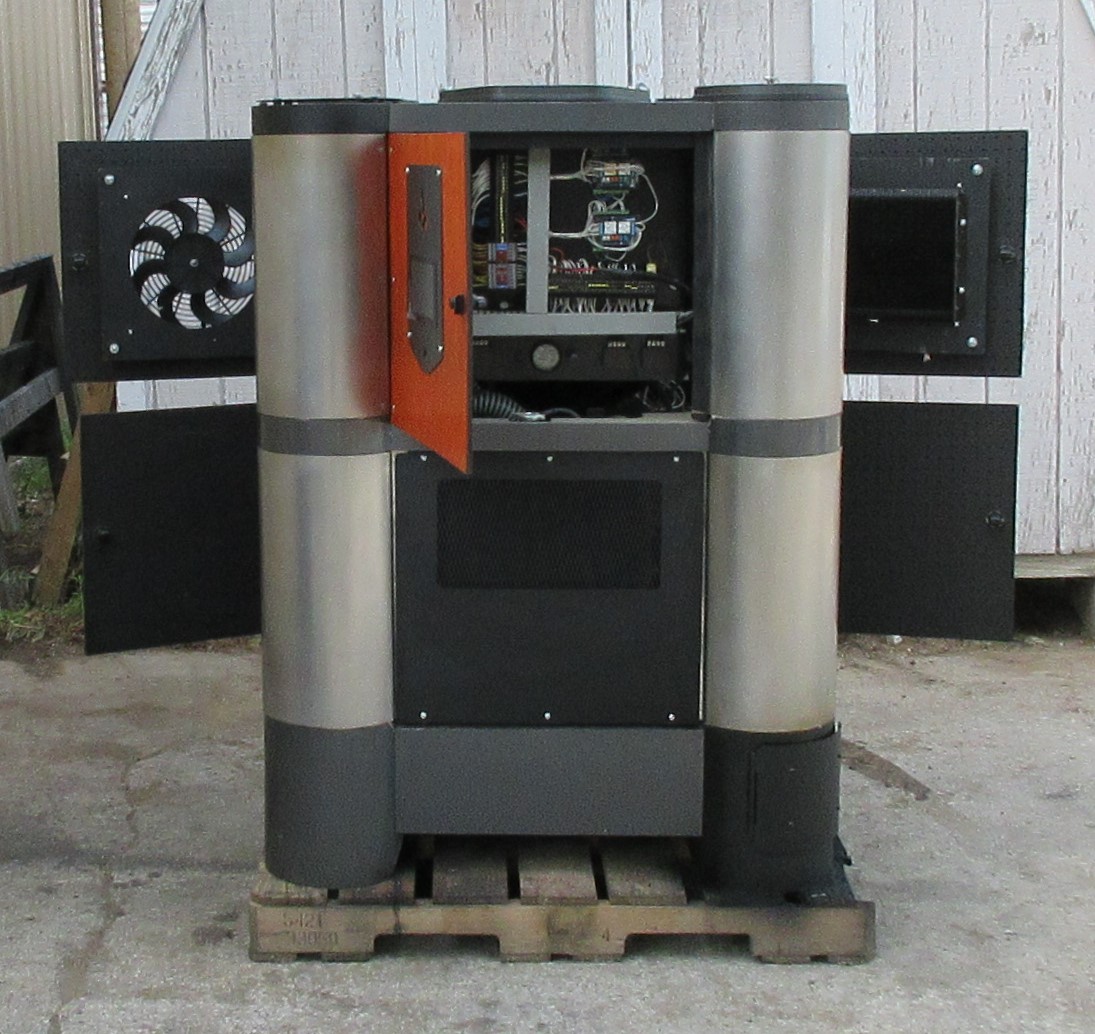
So I am finally FINALLY wrapping up the first FPS system. One last challenge this machine has brought to me and thats an exhaust leak at the custom header I built. Going to pull that off tomorrow and add some weld to the effected flange and grind it smooth.
The plan is to get that done then clean up for live facebook video and also demo videos for Youtube.
This thing is a beast!! If it were not for that exhaust leak it sounds like there is a little small block V8 sitting in there
I plan to go live later in the after noon / early evening if I can get the exhaust leak taken care of. I will be running the shop fully on this machine and running two 1500 watt heaters. the full shop lights, the 220 miller mig welder a clothes dryer and our typical shop equipment.
This thing now that I have all the automation working and tuned is making very good strong and clean gas. The original hopper poker mechanism I could not get to work and I finally scrapped it, I ended up linking a vibrator thru wall directly to the hearth and that is working perfectly. So this whole time (you can think of the hopper agitator as the fuel pump) I have never had consistent flow during the tuning phase of four months!! Argh!! . Well it is there now and its running good.
Those that may want to tune in the FB page is linked bellow. Not sure how that will play out, most likely I will come on live multiple times through out the night. The plan is to run for at least 3 hours. We just want to show how consistent this machine is with out any intervention.
Live feed is postponed for a few days. The engine has suffered tar accumulation from all the testing and tuning. I probably should have removed the crank case vent sooner and I think this was the culprit as the gas port to engine is open during flaring.
I did get the exhaust leak fixed only to find an underlying noise very very bad underlying noise. We were hoping it was just some lifter noise that it would recover from. Nope it was indeed a rod going out. It was weird as this would come and go. So I did not suspect the rod. I think the cause of failure was the oil pick up became saturated and this engine was starved for oil.
The good in all this is we found it before the machine left and as bad as it sounds. Its not really a big deal. Parts were less than 80 bucks and they are on the way. We will get this engine cleaned out and put back together as new. Now that the gasser is dialed in and the crank case vent is bypassed this wont happen again.
So Facebook live feed is still planned. Maybe a good thing because I want to show this machine sounding the way it should. It sounds beautiful.
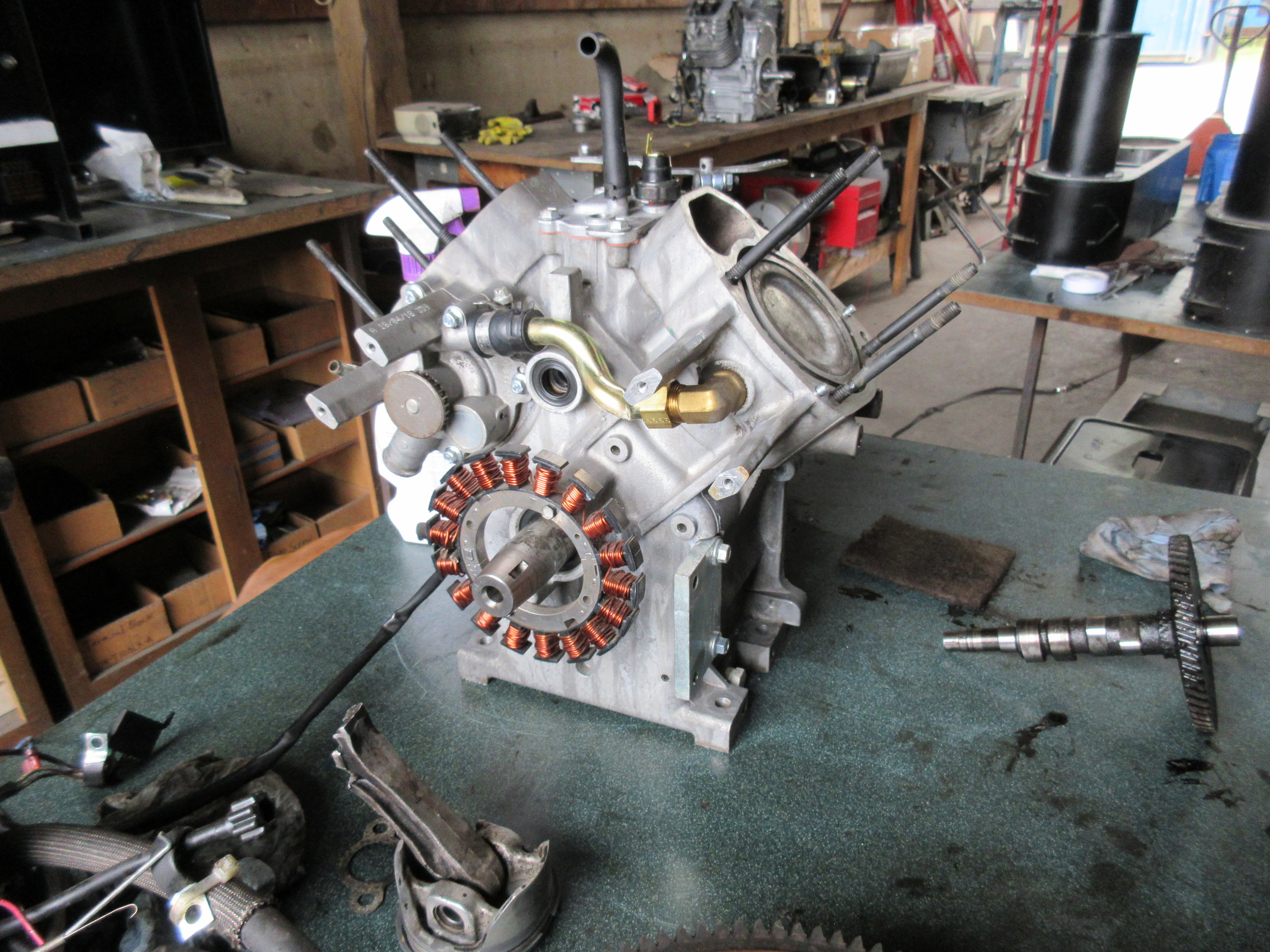
Engine block is all cleaned up, just waiting for the new connecting rod and new cam to arrive. If they come in tomorrow and are the correct parts Ill have this engine back in the machine by end of the day.
Yup 3000 dollars lucky!!! But thats the difference aluminum vs steel. A steel rod isnt going to let go of the cap as easily as an aluminum rod. If it were steel that engine would for sure be smoked. But on a small engine the rod is the weak link. Typically you can simply replace the rod with out crank journal damage. Just scrape the aluminum off and use emery cloth to shine it back up. Thats if there is not excessive wear.
You may need a better method too check for tar. Or is it posible your pellets were damp.Or posibly your char bed ran low before you fixed the hopper shaker, that happen too me trying too run pine sticks, no hopper shaker’ used up my char bed , went too heater mode, and cooked my ash door seal.Good luck getting the bugs ironed out on your cool new unit, how many watts you need too pull too keep the temps up, or maybe need more insulating designs added. Looking good.
No none of those issues, this was caused from earlier testing and tuning. The damage had already been done prior to getting the hopper agitator fixed. It just took this long, for it to reveal it self. Putting to work helped that along as this last week prior to this was the first real loading we put on the machine.
The crank case vent I just recently bypassed as well. This should have been the first thing I should have done. There was a 1/4" thick layer of tar sitting in the bottom of the crank case and oil pick up screen was clogged solid, nothing was getting thru it.
The gasser is working very well now that the shaker is working.The machine does not drop anything anywhere now, not even condensate. This is just how the proto types were and the machine you saw at Argos 2018. It ran for more than 8 hours that Saturday and only dropped a table spoon of amber condensate.