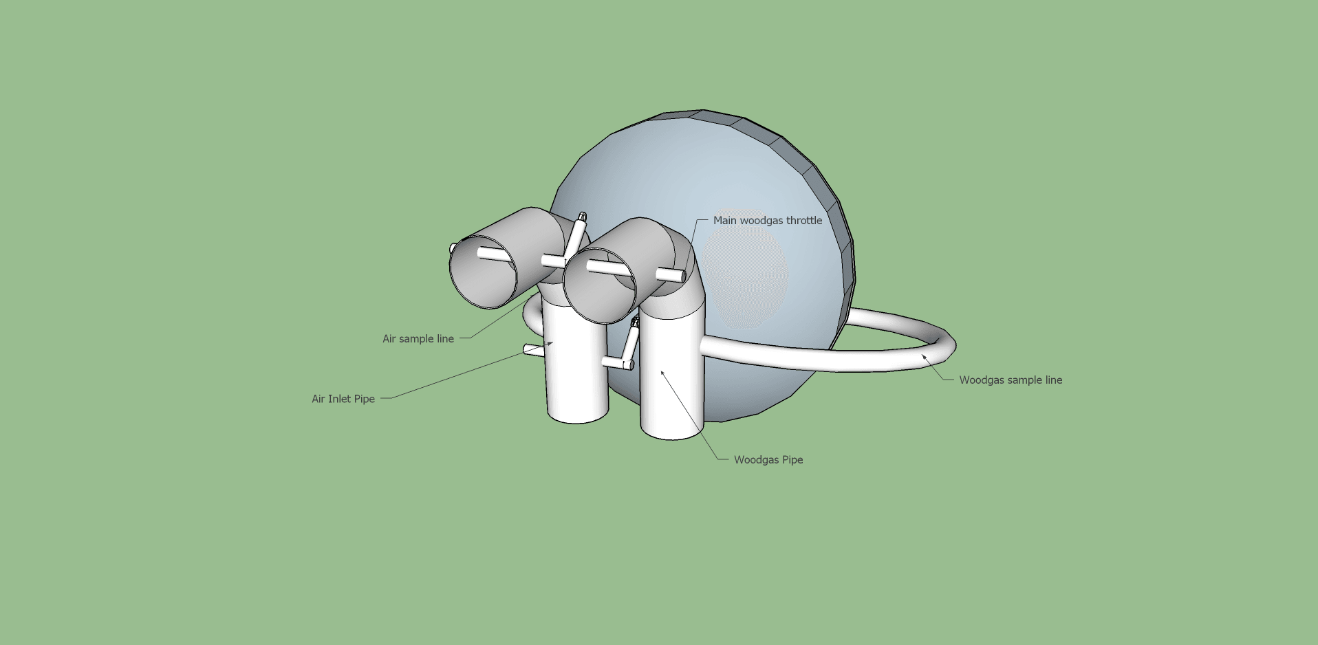
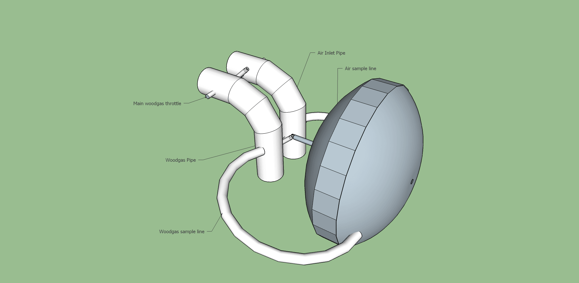
Bill Schiller gets credit for this tweak. To make the packaging and linkage a lot neater, I’m putting the air and gas lines vertical. Here’s the setup I’m looking at now:
That’s what I’ve said the whole time, it has to run on about 1/2" WC differential. That’s about a pound of force on my 9" unit. The only way to amplify is using a larger diameter diaphragm.
It’s not hard to build a linkage that will operate smoothly on this low pressure. Just keep joints and sliding parts to a minimum. In the drawing above there’s only one joint and the valve itself to contend with.
Hey Chris, a brother in law had a 6 inch diameter face vacuum gauge years ago that was meant for some non automotive application. It was 0 to 30 inch. If you had that connected to manifold vacuum. I’ll bet you could really tune your mixer linkages in. Analog is so much easier track trends.
Most aspects seem to have been touched upon; still there seems to be a vagueness about the difference between balancing arriving air/gas pressures on one hand AND AFTERWARDS doing the dispensing of the gases.
In a traditional T–type mixer, the handregulated secondary airflap has
2 functions combined:
Reducing the intake air pressure to the same as the arriving gasline pressure.
And
Dispensing the same airflow as the arriving gasflow.
The obvious can be said as:
Create THE SAME FLOW RESISTANCE for air,
as the arriving gas has to OVERCOME.
But,
With the membrane you can ONLY provide EQUAL PRESSURES
in the air– and gasline
BEFORE ANY DISPENSING and subsequent MIXING.
The dispensing happens with ganged TWIN flaps in TWIN throats…
Max,
Thanks for helping us get our thinking uncluttered. I use a little bypass tube around my mixing valve to lesson problems from stop and go, but I’m now looking for parts to build an automatic pressure equalizer. I’m thinking mylar for the diaphram and two shallow 3" deep cooking pans with wide rims for the chambers. Look for Stainless Steel Heavy Duty 16" Lasagna / Roasting Pan with Rack on Amazon. I use something similar for my safety filter. Gasket and seal with small clamps around the rim–no drilling or welding.
Bruce
In Africa you can always remind the keen listners, that this system, developed in Sweden in the -20 ies, has been used in France by the great GAZOGENE company!
Handwash, or truck rim sized membrane chambers were regulating the arriving air pressure to the gas pressure before dispensing and mixing them for BIG Mercedes motors, producing electricity for sale…
Hello MaxG, thank you for re-posting the above from pdf to plain text.
I like your new avatar picture.
Makes you, real, and friendly, and human. (not a parrot answering machine at all!)
Regards
Steve Unruh
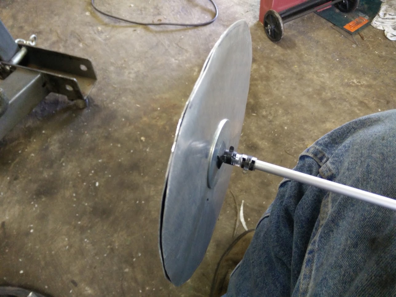
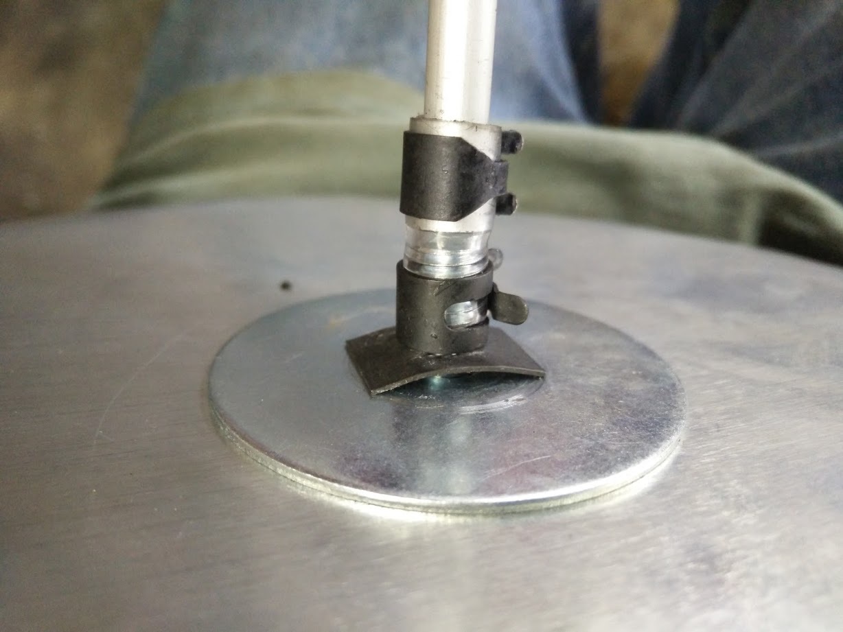
The two circles are held together with a 1/4" bolt, fender washers are used to hold the aluminum plates. Diaphragm itself is not shown, would go between the plates. I fastened the bolt to the rod by a rubber hose and two clamps. I couldn’t find a small enough Fernco coupling so I made my own.
The small black square is a “speed nut”, made from stamped sheet steel. This eliminated the thickness of a standard nut, which saves space in my setup. Every millimeter of length on that tube means less piston travel in the forward direction, since it cannot pass through the casing. The mechanism as it stands will have about 1.5" of travel.
Threading tools would have saved length and sturdiness, as well as “deassembliness”!
One stainless nut on each side of the fender washers…
Some low degree Loctight…
Hopefully the aluminium sheet peripheries are rounded and VERY smooth, in order to not “abrade” trough the delicate plastic.
The same goes for the flange inner edges…
A tight cramping periphery (between the sheets) will avoid the “plastic” to “travel” in and out in the radius’ direction. Maybe some silicone would make a “grip”, if the aluminium sheets are too timid.
Good ideas Max. I will definitely use some Loctite, and silicone, to make sure nothing moves. I also plan to set up the aluminum discs in my drillpress so I can sand the edges smooth and round .
Guessing you mean a shunt tube parallel to your air flap on a T-mixer?
Please! Drawings, sketches, pictures all make it easier to avoid failing fantasies about what the other is meaning and presenting!
16" pots! That’s for big powerplants like GAZOGENE! Are you going “Big Time”?
In the meantime, a few thoughts about the twin flaps, and were they are best useful, and where they are least useful; it is ALL about WHERE the DOMINANT resistant is, and is it under our control — or not.
Continuing, when finding the keyboard control for fattening fonts, instead of capital letters…
Max, I am wondering why we are re inventing this system. Do you already have it on your system. Hasn’t Dutch John given us details on his system?
Chris it seems to me like you are trying to get too much motion out of this system. Watching Dutch John’s the rods appear to move only 1/4 inch or so.TomC
It must have full control over the intended throw of the valve. Otherwise it can’t effectively set the air flap position; you can’t predict where it will need to be.
DJ’s mixer moved a 1/4 inch on a sudden throttle increase, yes. But the full range of adjustment is larger than that.
Yup, gasification will never be linear, we are getting close though. On my set up my in coming air vs gas ports are 1:1 and Ive watched it use just about the full range of the valve. Most of the time its about in the center, but especially when quick throttle changes occur it has to move the full range and do this fast.