I am currently working on the first 25 kW systems, we have two of these we need to get done before the end of the year. Then we will build demo for our shop and development soon after. These systems will feature our Generation 5 ES-IV gasifier with auger feed hopper. I am planning on a 40 cubic foot secondary hopper for this machine. The power plant for this build are the GM 4.3 ltr Vortec V 6 engines that we are converting to old style ignition and aftermarket intakes. I will offer this with the GM 5.3 ltr LS engine as an upgrade option. The generator head comes from Central Georgia generator they are impressive generators and wiegh in just over 400 lbs by them themselves, so yes this thing is going to weigh a little when complete. Secondary hopper will have heat exchangers built into it with both exhaust and secondary gases being utilized for recaptured heat. Im planning two systems that will go on the exhaust system. Before the exhaust makes it to the secondary hopper it will go through an exchanger to preheat the primary air leading to the gasifiers air preheat chamber.
So that is the basic over view, this machine will be very automated, I will get into this part of it later. No PLC is planned it all can be done with simpler methods. The auger control system I think is going to be pretty slick.
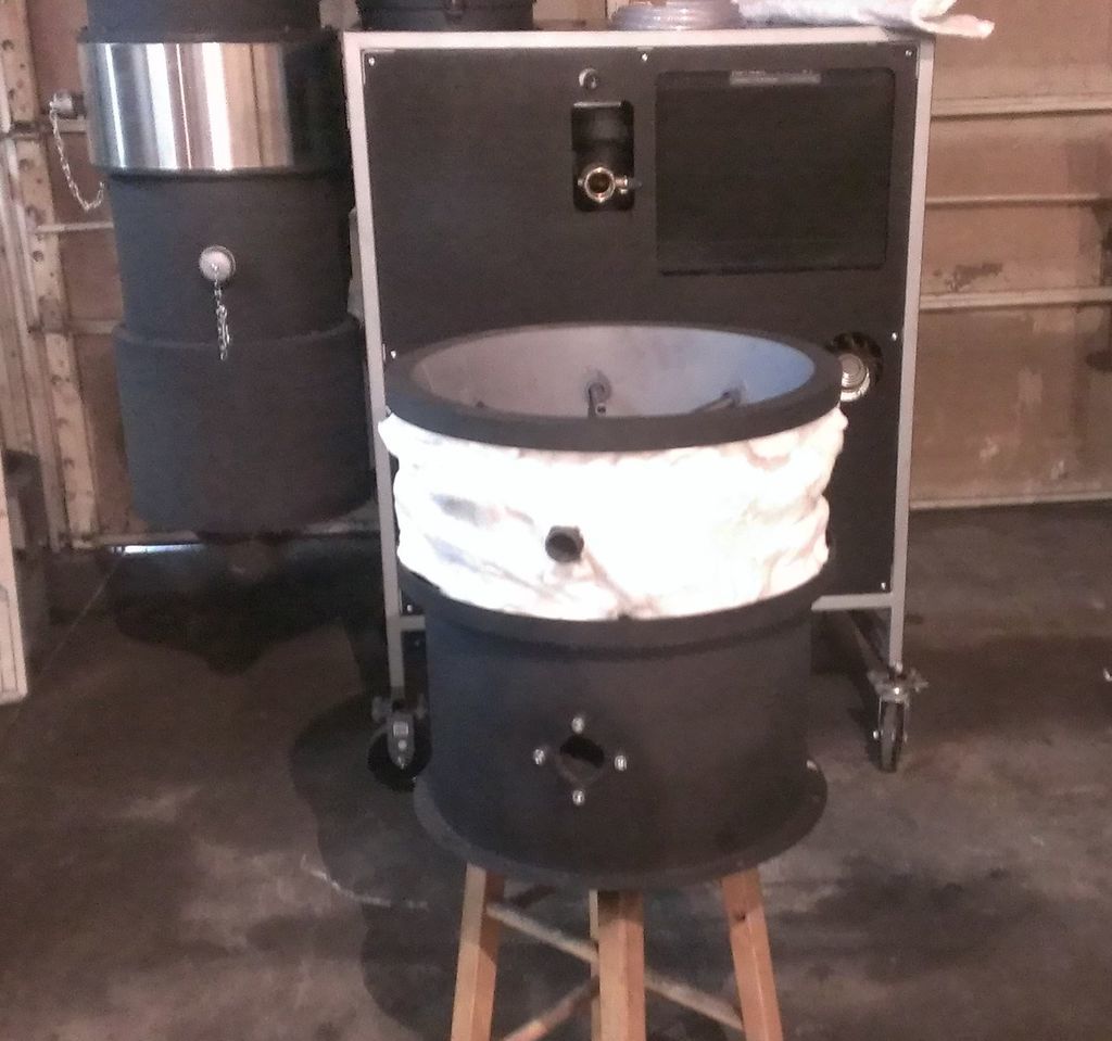
Bellow is the 5th generation ES design, this machine is going to a development laboratory.This ES-IV shown is the gasifier that is planned for the 25 kw system. This machine is quite evolved from where we started. This construction technique will give us the ability to offer the reactor portion in SS without building the entire system out of it, it also makes it replaceable. We are working in this direction and will offer complete SS versions soon. There are other features I cant discuss but one of the obvious features are the removable jets. The complete jet system can be serviced from the outside of this machine with out the need to tear it down or dig the machine out.
Hi Matt
Very nice!
May I ask what is you plan for the hopper feeding system ?
Have you seen my fuel drying tumbler ?
If you could incorporate that as a fuel conditioner and the feed from there in to the hopper ?
From my experience if you are running that 4.3 at any speed it is going to use between 100 - 250 kg in a 10 hour period, so the hopper feed has to be durable.
I got my governor controller form Tom Osborne at Central Georgia generator. They are very helpful.
Send me a link or some pics of the conditioner, Id like to check it out.
The hopper is going to be built sort of like a grain feed hopper. I am planning on a 6" auger with core and it will run the length of the bottom. These will have some very hefty drive motors with reducers to drive this. Im going to run piping through the hopper as a means of running the secondary gas and exhaust gas for heat exchange. Ill space this enough to allow fuel to flow through freely.
The automation is going to run off of a pneumatic system and timer. There is going to be a 12" air cylinder mounted to the primary hopper with low pressure pushing in the down direction. On the end of the cylinder rod there will be a plate or a steel cross mounted to it, that will push against the fuel. The air cylinder will have two prox switches mounted to it. When the cylinder extends to the lower prox this will trigger a timer, the timer will then output to the air valve and switch the direction for a set time. When the air cylinder triggers the top prox, this prox with then trigger the auger feed relay switch. The auger will feed until the timer hits its set point and then return to the extend mode and start the process all over again.
Yeah the 4.3 ltr is good durable engine and are very abundant, we are planning to use these as recycled engines. We will go through them and certify them and will warranty them with the machine. However, like the Gen I and II engines they are terribly inefficient engines. The Generation III LS V8 engines are much more efficient and produce almost 100 more HP than a gen II in the same CI, plus they don’t leak. The LS engines can be converted to simplified ignition systems with an MSD controller and an after market intake. The 5.3 is what we are planning for our demo and should actually have enough power to go even bigger to get us into the 50 kW range.
Hi Matt, If I where you I would consider keeping all obstructions out of the bin, it takes so little to start forming a bridge. A double wall around the bottom section of the bin and insulation on the outside would still heat the incoming fuel.
Yeah I am thinking along those lines as well and we will not have time to proof this out so this may be the direction we will go.
I think on our demo will experiment with this, the hopper is going to be very large so there should be plenty of room for the tubes and I think this will have a better heat transfer. Also with the tube system it will be an easier way to clean this system, I am planning on a simple removable cover to cover the ends. So yeah this part may come later.
The insulation will be a must with an outer chamber type design to be most efficient.
Hi Matt
Here is my youtube video of the whole system.
Just a thought with the pneumatic ram, the push rod it go unit to get pretty tarred up and jam.
How about a weighing system under the whole fire tube, hopper heat exchanger that triggers your feed auger?
Or I thought of a proximity sensor in the hopper ,but it would have to work on ultrasonic versus light, to get through the steam, smoke and tar?
Will let the grey matter stew on for a while…
I have a chain that runs from my engine to the hopper to create a vibration in the hopper, it seams to help prevent bridging.
The cylinder shaft will have an accordion boot to protect it from tar build up these can handle the heat as well. Besides it has to work I already bought all the automation components. Its all laid out in my living room lol. I did ponder the weighing and the ultrasonic sonic sensors, but with out knowing if they would work I decided the air cylinder is a for sure bet. There are counters made for the augers too but you would then need to time the system in between recharging. I want something a bit more consistent than this. Plus the air cylinder will push on the fuel and will have adjustable pressure. So I think this is going to help with preventing bridging as an added bonus.
I dont know if this has been posted else where, but here is a link to automation direct. These guys are for guys like us
If your feed fails for some reason or you run out of fuel the top of the gasifier will get much hotter. You can use that as an alert as it rises and shut down the engine if it gets too high.
Yes that is a great idea, yeah that part I haven’t quite figured out yet. Ill get another thermocouple and that is what I will do. Thank you guys for your input.
If you haven’t played around with them as yet an Arduino micro controller is very useful for jobs like that. The feed auger on my gasifier sometimes fails to start due to a bridge between the end of the auger and the switch that senses when the fuel has dropped. Now I have an Arduino connected between the switch and the motor, every 30 seconds after the switch closes the Arduino runs the auger for 1 second. This saved me a lot of frustration, For anyone not familiar with the Arduino just Google it, there is massive amounts of info on the net about them.
Hi MattR
I think you are absolutly correct on your GM Gen III LS engine opinions. When I last worked 2006 as THE used car tech in a very busy large new multi-line car dealership these the ones out od 200 vehicles a months at 3-6 years of age I had to do the absolute least amount of engine work on to prep for resale. Followed up with a year and half in a very busy indepedent shop 2006-08. Same thing. As you say - no oil leaks. No water pumps. No long worn rattling timing chains like Chrysler/Dodge/Jeep/Ford/Nissan; or NO time aged out T.belts like in Chysler/Ford/Nissan/Toyota and most all others. GM Gen III LS’s V-8’s were spark plugs only later at 100K+ but WITHOUT the PITA Ford Modular engines four threads only/stripping spark plug holes a-way, way down deep. No Dodge deteriorated hidden lower intake oil sucking/vacumn leaking floor plate gasket.
I think the GM Gen III LS’s will prove to be the last produced durable North American woodgas go-to engine series.
On your automation don’t overlook and forget the roller end spring arm MicroSwitches. Very very high quality and durable. Able to take severe enviromental abuse. Able to handle as high as a 10 amp switching loads directly. Make your own ramp triggers with weld build-ups.
Woodgasing developing helping out back in late 2009 I caught the tail end of a months in designing and building ~25kW/th bio-mass geek system. By the time the phone call after phone call of multi-users many better ideas demanded changing specifiacations has finally been cut off the bid buget was 95% used up with still all of the control systems wiring and batteries/charging yet to do. Down to just 10 day to a cross-continent delivery date with a daily bite clause too. System had a Bio-mass Conference schedualed roll out. Needed 12 and 24 VDC; 115 VAC for the different contol and controlled motors, lighting and power outs and stand-a-lone starting up, warming up to 17 kW/electrical producing capability. And all of this on a Hurricane weather resistant trailer mounted system. By going old school with HD 15-20 amp troggle snap switches. Rolls of 2 and 3 wire severe weather and abrasion resistant direct connected power cording was I able to pull it off. Five days only to source all; premake harness runs; batteries boxes and do discrete subsystems testing. Then a mondo untill 3:00 AM 8 hours of wire in install final harness cut end terminate for final day whole systems testing, touch up paintings, cleaning up before shipping out. I came in including two large 12vdc FLA batteries, a separate 60 amp 12 DC charger at 3% of overal budget and everything worked fine first time.
NOT using neat lighted mini-switchs then requiring a relay and a relay socket all of the extra wiring and termination; and sans any electronic mini-sensors and switches requiring signal boosting/signal digitizing is what pulled it off.
Color coded monkey-see, monkey figure out wiring and failures electrical direct diagnosing then too.
Ha! They even got a 3 vdc laptop charging port and 2 hours of system off 115 VAC at 1000 watts thrown in on the deal.
Switches intuitivly UP for on. Intutivly Down for off. Send a cave man out to down sweep ALL for sysems shut off and a marine Pergo knob twist for systems power isolation. I only regetted not having the post installed time to be able to boat trailer like solder seal all of final end W roll crimped terminated harness run ends.
Automation can be a three or more deck of the game of 21 if you let it run on you.
Rural Americanism: “Everthing does NOT have to be such a big damn deal.”
Yeah Im doing everything I can to stay away from PLC controls. But I don’t think it will be long before we will need to go this route. Yes the toggle switches to relays and things like this really take a lot of time to wire up. I am going to industrial type relays and the multi function controllers for now. Being able to just terminate at the component and terminal blocks should really help speed things up with all the wiring we will need to do.
More to come, lazer cut parts will be here on Wednesday and I have a new guy starting tomorrow. We should be rapping up the two ES-IV machines by then and then we will be full force on the 25 kW machines.
Thanks Patrick, Yeah that looks like a great idea, yup I think you will see a version like this coming soon. Yeah this could easily solve the air blow by problems.
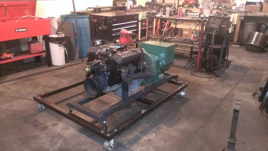
Things should start to come together pretty fast going forward. We mounted the engine and gen head up yesterday and will work on the cage today. I have to machine out one of the lovejoy couplers to direct fit the crank of the 4.3. As soon as the reactor is done we will mount this and Ill get to work on the secondary hopper and auger system. Can wait to see this thing complete.
Hi Patrick, yes there are 4" steel casters under neath. This makes it easy on us to move the thing around too. Im considering selling these big ones with a trailer package.
I rolled the hopper for this thing today and just set it up. to mock up to see what its going to look like when done. It looks enormous and that hopper still has to go up another 18" to make room for the auger system. We are going to install stairs that will go over the gen head for easy loading.