I think you are right on that.
I just took some temp readings and it is just above 160 at the top and cools as the exhaust stream goes down. When I take fuel out of it, the fuel at the bottom is soaking wet as you stated. I just take whats on top and keep replenishing. But is something that could be made better. Simple shell with insulation with a removable bin.
Not going to help. Put a heat exchanger between the engine and the fuel hopper. Heat the outdoor air and blow that through the chips. Then everything will only get drier.
Hey MattR
The generator portion on one of these golfcart Hitatchi’s and the US Delco Remy equivalent are very low output. Say 10-20 amps for a 12 volt system. As enclosed, non-air flow cooled they have to be.
As stationary wound field, segmented commutator with all output amps out through the brushes, DC generators these need a min two unit regulator control. One control portion to cut-in and cut-out the armature from barttry connection to prevent battery reverse current draining at zero RPM. The second control unit portion as the actual system voltage detecting magnetic field supply control.
And if the unit was ever hooked up to try and charge a big battery, or oversized bank, these types of non-smart generators will just keep cranking out the amps, overheat, and melt out their commutators solder, or, heat cook their armature winding’s insulation. Why the good generator unit regulators back-in-the-day used an added in a third control section to limit allowable amperage output.
Just all old generator experience/knowledge, now obsolete.
One of my more frustrating experiences was a couple of years ago trying to walk a fellow on another DIY power forum to get his to work right to safely long term generate.
It starts with understanding “A” circuit (old GM, Chrysler, R.Bosch some Japanese) versus “B” circuit (Ford, Lucas and other Japanese) field controls and goes on from there.
So . . . possible for your on-board starting battery. But cost you an added-in $$ control regulator. Wiring in at least three more reg/control to generator circuits. Then in-field with system aging troubles writing a diag./repair manual.
Lot of work/sweat /risks for those few watts.
Anymore; on an in-some-way will be AC power system anyway, I say just get a plug-in battery charger and go see-do simple. Then, if/when that charger dies - replace that. Then that charger availble for other systems battery charging. ATV’s. Motorcycles. Boats. RV’s. Tractors.
Regards
Steve Unruh
Tom and Arvid:
There are several companies that make these PM generator.
I did not keep any information on them because I wanted something for RV use ( as a product to resell and there was no option for 24 or 12 volt ).
But its a PM unit slow it down and the voltage drops ( Could manage 24vdc but 12 is a stretch ).
I could rewind one but that is a lot of effort for something I can not sell.
There was a parts seller On Alibaba that sold theses, maybe you could just buy the head less the engine.
BUT shipping is a killer unless you ca fill a large order.
You also have to haggle with the Chinese for a price.
The shipping is just like Ebay now and the main point they try to screw you on.
I buy most of my heavy things from a fellow In Thailand because he gets me better deals.
A Honda Inverter generator would probably be a good place to start if you want to make something like this.
The electronics fry but you can salvage the generator parts.
SteveUnruh:
I agree with you about the fine voltage and current regulation of a Powered field.
But you can get the same thing with a charge controller that limits engine RPM.
A generator is a funny creature,
It does not know when to stop, thats why they added the current limiting section ( to protect it from itself trying to supply more amps than the windings can handle in an overload condition ).
An alternator is somewhat self limiting in current, but this comes at the price or a wider range in field current VS load requirements ( to overcome the synchronous reactance of the stator coils ).
There is also the rectifier section of the alternator that replaces the low voltage cut out on the generator regulator.
This is why Generator regulators are larger with 3 sections and Alternators have only 1 ( voltage control excluding the rectifier bridge )
In booth cases you need to put power into a field.
In both cases you have a narrow window where the magnetic core density and RPM are right for the most efficient conversion of mechanical power to electricity.
Once you are outside these windows small alternators and DC machines see their efficiency drop bellow 50%
1 Like
Ok I just threw another iron in the fire! The little generator with the M-1 we built is going to be our test bed for a lot of new development I have been planning for this summer.
One of the items on the list is turboing the system. However, not a traditional setup or even to create any boost at all. The plan here is to eliminate vacuum pressure in the gasifier system. This will be Arduino controlled. There is a number of reasons for this, one is to make condensing moisture more efficient and the other is simply alleviating the engine from pulling a vacuum. This will also be for more advanced stuff, Ive really been interested in the fischer / tropsch process and also the Sabatier reaction. So hope to get to tinker with this too.
Here is the little turbo I have on order;
http://www.ebay.com/itm/171240615758?_trksid=p2057872.m2749.l2649&ssPageName=STRK%3AMEBIDX%3AIT
6 Likes
So are you going to use the boost side to pull the vacuum on the gasifier and “push” syngas to the engine?
1 Like
No Im planning on metering in air into the intake of the gasifier. It will be controlled to have a static pressure, or a slight vacuum during loading, I don’t want to have any positive pressure on the machine just want to alleviate the vacuum. The waste will get directed back to the engine’s air intake and also our 3rd stage reduction also new in development.
I could go a less expensive route for this part, but we will need some pressure for the Fischer / Tropsch process.
I’m all for research and innovation, but F-T is big mountain to climb. There have been people that have spent 10’s of millions of dollars on this with nothing to show for it. You likely know this, but the biggest challenge you may have is the gas composition of woodgas from an air-blown, atmospheric gasifier. Over half of the gas is just nitrogen (N2) which carries through from the atmosphere. Most people working on F-T are using steam or oxygen blown gasification that results in syngas with much larger relative volumes of hydrogen and CO. Good luck, and I would be very interested in meeting you sometime; fellow Michigan boy here working on larger scale gasification of solid waste. Cheers!
2 Likes
Yes I know but we live and learn. It will be fun and there might be something we can learn from it. You and all others are welcome to the shop anytime 
3 Likes
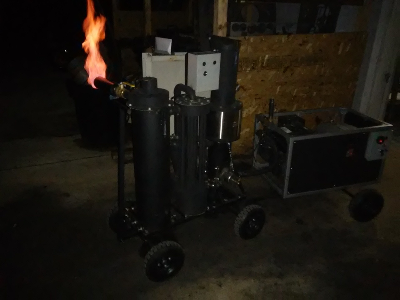
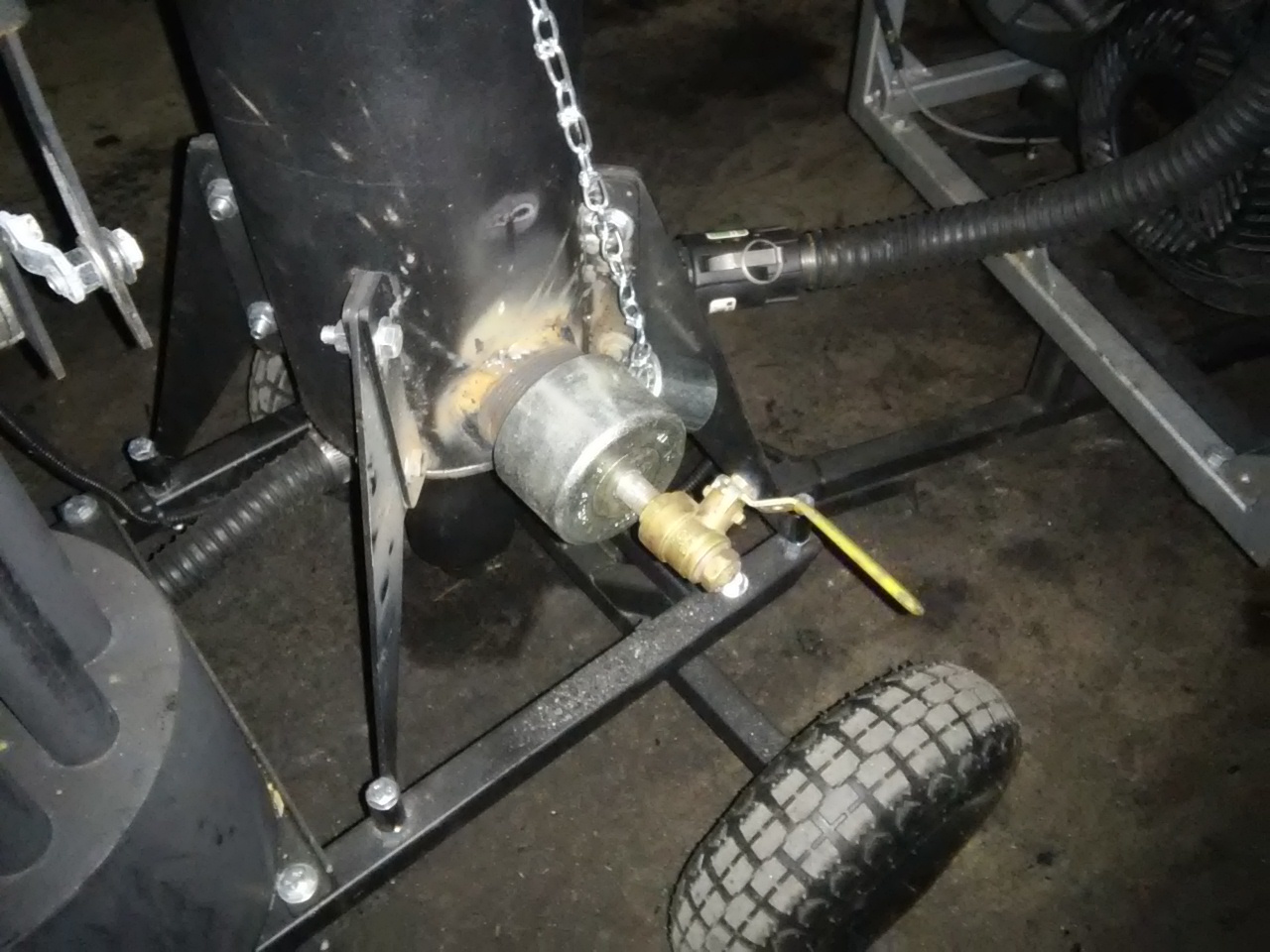
Some of you that made it to the event may have seen tinkering with this little machine. Couldn’t get it to work I was working on this and had to finish building it at the event. So I didnt get any run time here or even a chance to debug it. Well of course there was leaks lol and then some issues with the servo. I think the rain might have wiped it out.
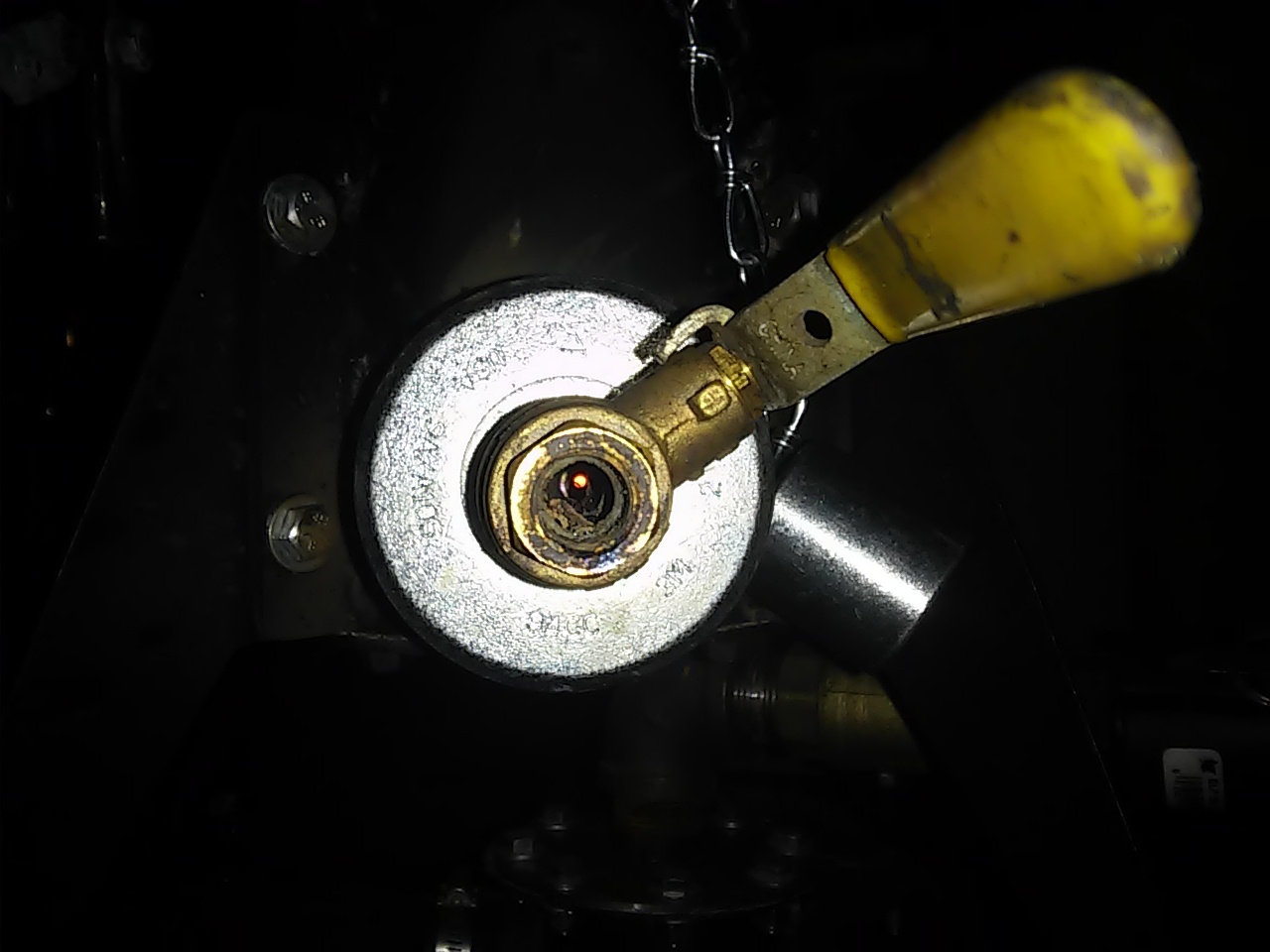
So I took some time to fix it today so we can get started on new development. First thing I wanted to try and was an easy one; is adding in a simple fire system into the ash pot. Reasoning for this is our customers that want the big systems do not want to mess around with emptying condensate, media filters or the ash on a daily basis. So why not just burn it off and reduce it to ash, if I can get this to run linear to the char yield or just below this should greatly decrease the intervals for ash clean out. The bonus is this will also add some efficiencies and add heat to the primary and secondary reduction systems. When I get the turbo air will get branched off the intake of the gasifier and Ill add in the EGR then. I may still implement a removable auger system to this as well.
So far this is working pretty well, Im keeping my distance though lol
2 Likes
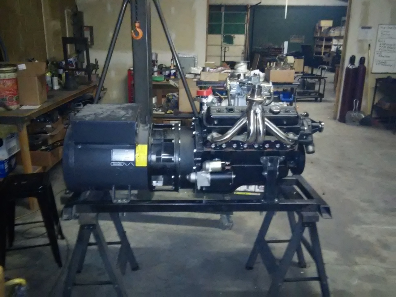
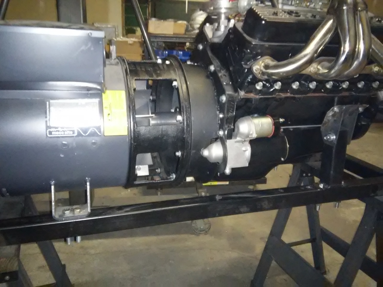
More evolution, so as you know we build our generator systems in house. Im not 100% on this but I think we are the only ones. This maybe as building a generator in this caliber of size is well a bit of a challenge. One big challenge is mating up an engine to the generator head. In the past we specially machined LoveJoy spider couples, this worked well but this limits us to the more expensive dual bearing heads and limits whats available. It also just did not look manufactured. So the challenge, is to source an SEA 4 bellhousing that will bolt up to the GM 90* bolt pattern. There were some options out there; however, there were just way to many unknowns for a very expensive part that no one could guarantee would work for us.
So I built my own!!
What I had to do was build a very high precision fixture, I purchased a Chevy to Buick bellhousing adaptor plate to use as template. This is so we can very accurately transfer the GM dowel holes over to our bell housing plate. We CNC the both the SEA 4 flange and also our GM mnt plate. But the CNC is not quite accurate enough for locating the dowel holes. We need to be less 0.001" center on those dowels so this plate makes it very easy to do. I built a fixture system on our mill and dialed this in to less than a thou tolerance. I built another plate to locate holes for the generators flywheel to the GM pressure plate. Im using the 11" pressure plate use clutch bolts holes and dowels for mounting this jig. Then we transfer punch those over, drill and then tap.
Once this is all bolted up we then align the rotor shaft to the engines crank to a thou our less.
End result is it looks like we bought it!!
Now that we have this fixture we can duplicate it and this opens up a lot of different options for us.
9 Likes
Looking good Matt !!
Amazing…!
Jeff
P.s. I forgot that I have to post at least 20 words.
1 Like
Hey Matt, nice work, looks very pro. Had a question on the mounts why no rubber? I have a 17k, and a 25k gens both are 4cyl. engines with very heavy rubber mounts, not questioning your engineering, just wandering if it is needed to keep from cracking the frame. Al
1 Like
The frame in the picture sits on rubber mounts. The engine and generator need to be solid to one another or all kinds of really bad things will happen.
This will sit on the main systems chassis on six beefy isolation mounts 
1 Like
Great accomplishment MattR
Look into the different available commercial power transfer couplers available.
Very hard to get, and maintain the precision needed to not an a few hundred/thousand hours not knock-out/wear-out a bearing. Why OE’s use a flex plate coupling.
Regards
Steve Unruh
Yeah Steve already been down that road. Nothing is standardized and none of those manufactures could give us a solid answer on what would work. We would just have to buy things and through parts at it until we got it right. By that time we would be bankrupt trying all the different housings, star drives and everything else that is available.
This fixture I built is very accurate, I have now dedicated our mill for this job. When this is all bolted together I dont rely on dowels or anything to center the rotor to the engine. We dial this in manually with a 0.0001 dial indicator. So it is perfectly centered when done.
Oh believe me I know all about bearing mis alignments. This was my job when I travelled as a service tech. The machines we built were high precision multi axis grinders. The Z axis on non counter balanced machines had major issues with bearing and ball screw failures. When I first started my position, I found that there were some discrepancies with the alignments this didn’t go over well with me being the new guy vs guys in the shop and engineering. haha. When the machines were manufactured they were aligned with the Z axis column laying on its back. Gravity is a very bad thing when it comes to high precision and was affecting the alignments pulling on the ball screws and also affecting the readings of indicators when sweeping surfaces. I developed my own tooling for working out in the field to perform new alignments. The company completely redesigned the drive systems and also alignment procedures once my realignments stood the test of time. This was major battle for them.
1 Like
Excellent answer MattR.
If I may re-phrase:
“We build our systems one at a time, Craftsman one at a time individually hand dialed in to not need these mass production fixes.”
Pride converts the worker into a caring craftsman.
I had my unit builders actually in metal sign their works.
Best Regards
Steve Unruh
2 Likes