Always nice to see the little MG running on the black stuff Bruce , well done again .
Dave
Always nice to see the little MG running on the black stuff Bruce , well done again .
Dave
First class job Bruce! Really, really neat, and cool.
Thanks for the ride and walk around on your MGB. Enjoyed it very much.
Bob
Another charcoal gasifier, well done and extremely nice build imo
It drives well! Good takeoff acceleration. Thanks for shareing.
Hi Bruce. I have being following your project and ended up amaizing!!
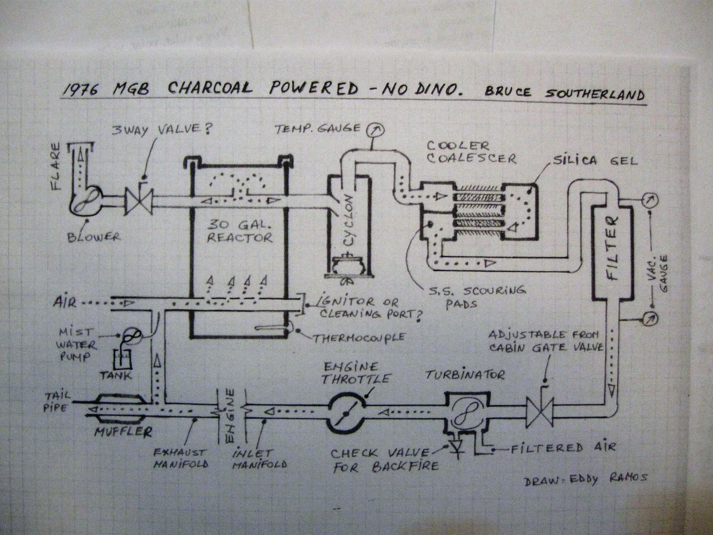
For my own comprehension and for other crew members of this site I made a rought drawing of what it seem to me how your system works. I am submitting this drawing to you and if you wish you are more than welcome to make any corrections, suggestions, etc.
Trully yours.
Eddy Ramos.
Eddy,
Thank you!
Nice sketch. Mostly right.
The “adjustable from cabin gate valve” goes on the “filtered air” side of the gas mixer (turbinator).
The 3-way valve connecting the reactor to the flare, alternately connects the flare to the gas mixer (turbinator) through a bypass hose with its own shutoff valve. This bypass function fills the system with chargas before starting.
The “IGNITOR OR CLEANING PORT?” has a shutoff valve that is actually open while running and is the entry point for the water mist.
Your pipe from the exhaust to the air inlet needs a gate valve to control the amount of exhaust gas recirculation (EGR).
Finally, the backfire check valves are actually in a chamber that connects the throttle body to the intake manifold.
Just for completeness, please note that the nozzle or tuyere is a thick-walled copper tube.
Hello Eddy, thanks for the sketch!
Hello Bruce, I tried to find it in this thread, but I have missed it. What kind of filter media do you use in this system?
Thanks,
Til
My filter is a large (8" X 18," 120 square foot) paper spa filter cartridge covered with 5/8" 65 PPI oiled polyurethane UNIFOAM.
Hi Bruce.
Thank’s for the quick response. I believe some of the crew members of this site will greately appreciate it.
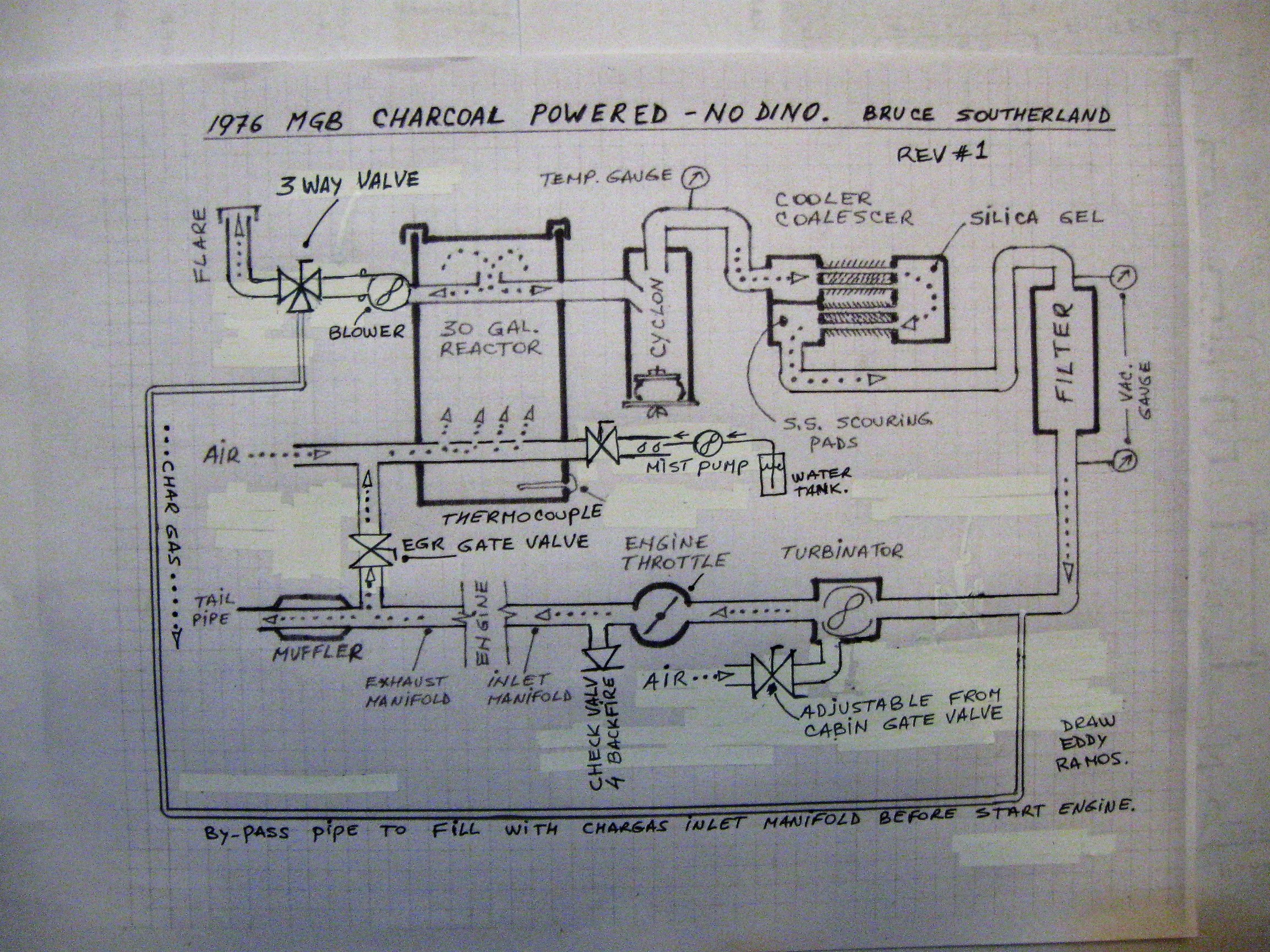
I have corrected the 5 items you have pointed out, please check it out. Fill free to make any further correction/suggestions.
Regarding the 6th item, justo to make this great I will suggest you, if you wish, to make a technical list of the different parts. For example:
The nozzle is a copper pipe outside diammeter of 1 1/2 “, inside diammeter of 1”, meaning that the pipe wall is 1/4" thick, with four 7/16" holes tilted 45 degrees for easy cleaning with a poaker.
The pipe inside and at the top of the reactor is galvanized steel of 1" diammeter. Same kind of pipe from the cyclon to the cooler/coalescer. From the cooling/coalescer the pipe is plastic of 1" diammeter… etc.
And at last to make this just perfect I will suggest you, again if you wish,
Excellent effort to document builds.
I really appreciate schematics, and dimensioned cross sectional drawings. As @TomC often says, a drawing well laid out can convey a huge amount of concise information.
I work best from dimensioned cross sectional drawings, it’s the way all complex metal work is made in industry around the world.
Work to document this build is much appreciated, a materials list is an excellent idea, and I hope this style of summary is continued with other build threads.
I second Garry. The skech is amezeing. It wuld be a great idea if we make a topic just for skeches, where every sucsessfull build wuld be drawn in schematic and cross section like this one. If Eddy wuld be in for a group project, l am more thain happy to document and skech my Mercedes for him to skech. I know he already had one for Dons Tracker, so there is allso Garrys Ranger, Davids tractor…
Thanks for the great build and drawings. I can really appreciate the drawings, it helps bunches in showing what’s what and where it sits in the sequence.
Beautiful sketches. Really close this time. Move the blower to the other side of the three way valve and reverse the direction of the bypass arrow. The bypass hose connects to the inlet manifold so that everything is filled with gas including the mixer and throttle body. The blower first draws gas directly from the reactor until good gas is produced then the valve is switched to draw gas through the cyclone, cooler, filter, mixer, and throttle body. This little trick keeps startup moisture from fouling my system components. I have a shutoff valve on the bypass just below the three way valve to turn off the system flare and prevent air from being drawn back to the manifold from the flare and blower.
Yes, I too have noticed the phenomena of harder starting on charcoal left in the reactor. I poke up through my nozzle ports and scrape or vacuum out the dust that falls. I’m hoping that Kristijan’s slotted vacuum nozzle will work to clean out charcoal dust from around the tuyere before refilling. The accumulating charcoal dust may be the culprit. The problem is not “plain carbon.” High temperature plain carbon charcoal is the best fuel and will give good gas immediately.
I am a very big believer in Skizzes or sketches. You have done an exceptional job. You are lucky that Bruce is so acceptable to you doing this. I have mis-interpreted the written description and have been reprimanded for making changes to the design. Not all people are so willing to help you get the drawing correct. Again, an excellent job of making a visulization of Bruce’s build. TomC
I noticed one other minor change. The scouring pads come first to coalesce any tars or moisture and the Silica Gel is there to help pick up any remaining moisture that might foul my paper filter.
This is an experimental hodge podge. Criticisms and suggestions on how to do this better or differently are welcome.
One suggestion - do you think the turbinator is needed? It should be possible to size the conduit for laminar, or turbulent flow. Actually by the time the mix arrives in a cylinder, I doubt it could remain unmixed.
The turbinator is NOT essential. My Toyota pick up ran fine without one. However, I came across a research paper claiming significant performance improvements for producer gas engines when using a tangential air/gas swirling chamber. Also this MG engine doesn’t have the greatest intake geometry. So, I decided to give this a try to eliminate the reported laminar flows where such mixing is absent.
I would be interested in learning about the conduit sizing solution. I was barely able to squeeze a mixing chamber and throttle body into my space. Tell me more about what you have in mind.
Porting, cam changes and increased compression ratio can also improve performance. Of course a supercharger would be best.
Are you satisfied with the work of the silica gel. How much do you use? And how often do you renew?
thank you
From reading years ago I recall that there can be two types of flow through any conduit, laminar, and turbulent. The type of flow depends on diameter of conduit and the velocity of flow.
This predictable effect can also be used for cooling . I will have to find a source article I read that was directly about gasifier design parameters.
Edit: Found it!
http://www.woodgas.nl/GB/diy.html
Tubing diameters depend on the gas quantity, but also on the temperature. In most tubing, we want a laminar flow (< 5 m/s). In some tubing we need a turbulent flow(> 6 m/s). Unfortunately turbulence raises the pressure drop in the system and reduces the filling degree and with that, engine power output.
To determine the tubing diameter, we first calculate the gas flow in liters per second. “We had that number already?!” you will notice; indeed, the quantity of cold gas. But since the gas is hot, an increase of volume occurs. We recalculate this flow using a conversion in Kelvin. 0 degrees Celsius are 273 Kelvin. 350 degrees Celsius are 273 + 350 = 623 Kelvin. 18.4 [l/s] at 350 degrees becomes:
(623/273) x 18.4 = 42.0 [l/s]