Oh, you meant the cooler. I forgot to mention that I coat the inside with used engine sump Canola oil to stop rusting. That is why some of the dust sticks to the walls and doesn’t fall down, Next time a stainless inside tube would be my choice. I’m thinking; if the inside tube rusts, it might wear the rubber seal when installing or removing. But I bet it would be microscopic, in other words not a real problem.
Hi Jeff.
You asked me to make you a clean sketch of your producer so I have studying this topic from the begining, and follow the different modification that has suffered your desing…when finally in post # 85 I saw your skecth.
Please I will need some basic info:
The type and size of the engine that this producer feeds, and what kind of vessels are you using for the top hopper and for the reactor, Some sizes??
BTW: I think that the reason why the reactor work better without the spacing wires is because the inlet air has to squeeze between the pan lip and the bottom of the reactor this way he air is being better preheat (hotter) because 100% of the air is “licking” the bottom of the reactor that is hot.
Jeff
it is not possible for everyone to imagine new configurations 
Thierry
Yep.Yep. Well, well said.
Efficiency mania of each separate step DOES not lead to “better” usable results.
Just spends a lot of non-replaceable time and money’s.
Every single failed 1990’s idealized “better” bio-mass systems failures can be traced back to sinking from obstinately insisting on single failure point better-efficiency blockages. Gas turbines & Stirling cycles engines versus proven IC piston engines. All-biomass systems capability hinted at by slit-hearths with formed “fuel-cubes” and/or plasma & fludized bed systems with ground particlized fuels versus just chunked woods and made and sized wood-charcoals.
Read these Idealization efficiency chasing’s and weep.
tree-farmer Steve unruh
Engine = 212 cc (6.5hp)
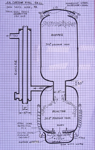
Top tank = 20 lbs propane tank, ~12" dia (~30cm), ~ 12" tall (~30cm)
Bottom tank = 30 lbs propane tank 12" dia (~30cm), ~ 18" tall (~46cm)
Center tube = 5" dia (~13 cm), ~ 3.5" (~9cm) between tanks, later I’ll see if I can find a photo to guess how far it protrudes into the bottom tank.
Cooler = 5" (~13 cm) dia outside pipe, inside pipe 3" (~7.6 cm) dia., forgot to measure length.
Air squeeze could produce some swirls that mix with the steam? I don’t know.
Hi Jeff:
Please find attached the sketch you asked me to do for you of your producer/cooler.
Best Regards.
Eddy Ramos (Argentina)
Eddy, your are amazing!
A couple comments:
The bolts, that help grip the refractory, are covered with the refractory. The bolts are not exposed to the charcoal or glowing charcoal.
No bottom/side clean out on the cooler. The inside tube is easy to remove, serves two purposes and no tools needed to remove.
Many thanks,
Jeff
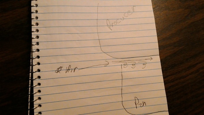
Where does the air come in? nozzle? what am I missing?
Al
When i first saw this at Argos I had a difficult time understanding what was going on. Jeff kept telling me and I still didn’t get it. This is what I left with and jeff can correct me (again) if I misunderstood.
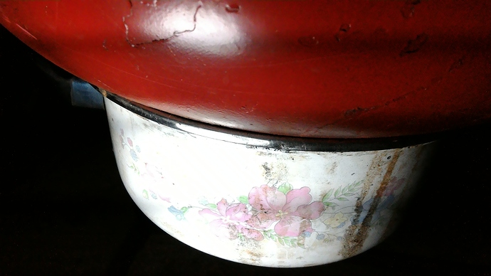
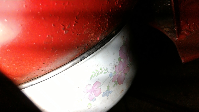
When running the pan underneath is held off the bottom of the producer a little ways allowing the air in at the bottom. Shut down the pan is sucked up to the bottom of the producer shutting off the air flow.(springs) It is so simple that this mind couldn’t see the forest for the trees. My mind was struck in downdraft mode that I couldn’t recognise updraft mode let alone only halfway up updraft. More hopper on top.
Ok Jeff you can now chastise me.
You were not alone on this design. It took me awhile to figure it out. It’s so simple it hurts. Makes me want to build one for my lawn mower tractor.
Bob
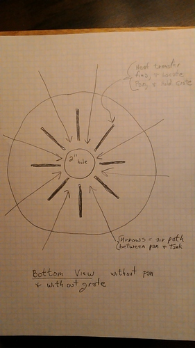
Tom, it might be my turn now! In my old age I forgot to install the wire spacers and it ran just fine. So, after it is running the engine I just put the pan on spring tight. There must be a space, just too small for easy notice. At shutdown, I just shut the engine off, that is all.
Hi jeff
do you have an explanation? why do you think the engine works better with this restriction?
can the reactor, in negative pressure, produce a better gas? a bit like a gasifier with a small nozzle vs a big nozzle (high speed vs slow speed of the air enter the gasifier)

Hi There:
Thank’s Jeff, Al, Tom and Terry for your commentas and suggestions.
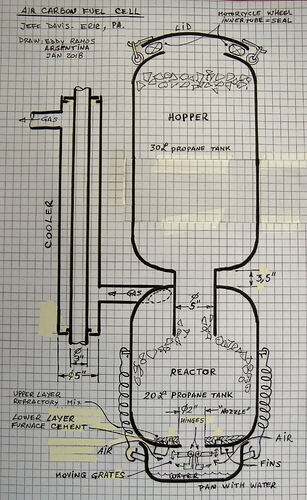
I revised the drawing. Please check it out.
Hope this is it.
This will be the Revision #1 of the “Air carbon fuel cell” drawing-Jan 2018. By Jeff Davis.
B.R.
Eddy Ramos (Argentina).
Ok got it, thanks. Now the next question is, what size is the air gap? Is it variable?
I need to remind that it seems to run as well without the spacer as it does with the spacer. I can not say, for sure, that it runs better without the space. What I can say is that I thought that it seemed to be a nice run and then I noticed that there was no air space.
I put a lot of effort to reduce the restriction in this system. Even the 2" grate hole is an effort to reduce vacuum. So, what a surprise to find out that it ran just as well capped up! Possibly vacuum concentrated at the point of reaction does help or possible Eddy Ramos thought that the air becomes more preheated by clinging to the hot tank. I do not know.
Yes, it looks good ! ! !
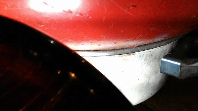
Saturday I’ll dig up a feeler gauge. We are looking at two as pressed surfaces touching, one painted.
This spot is ~ 0.020 inch.
This spot is ~ 0.010 inch.
And these spots (remaining) are too small for me to measure.
What if it has to do with steam. Under vacuum more steam might be generated in the pan. If so could this also be self regulating? More pull from the engine the higher the vacuum and more steam is generated. I do not know. This spring I should find a Pyrex bowl so we can see inside. Can I buy a bottle of coloured air to watch the air flow???
If you have a vacuum on the inside edge of the bowl and air is moving between the rounded edges with an opening in the unsealed metal edge. The velocity of air moving between the edges will open it even more until the vaccum drops and velocity lowers keeping it open. The same thing as air passing over a wing effect giving it a lifting force. Spring tension and bowl weight are going to be factors in this.
Bob
Hi Everybody.
I have started a new topic with a collections of my drawings, part list, spec’s sheet, and/or operations procedures, it is call: “Drawings of charcoal gasifiers for vehicles”. In this new topic is included the work I have done for this topic. Thank’s Jeff.
Hi Bob!
24.5.2018
You are totally missing the pan diameter!
The pan diameter tells the “piston diameter” of the pan. The pan bottom surface
is = the piston surface.
Piston surface X pressure difference (outer/inner) makes the pushing force upward.
The pan-edge dynamics do not contradict the “piston pressure” generated
by pressure differernce in/out - side the pan…
Oh the light just came on, thanks Max. I miss it again, but it is great to have people like you help us out.
Bob
