Hi all,
I was hoping to ask for your help. I’m making my first try at building a gasifier, starting from the Gary Gilmore Simple-Fire plans. I believe that more than one person on this forum has warned against the tendency to tinker or innovate on a first build, and I will confess that I have definitely fallen to temptation here. All the same, I was hoping that veteran builders on the forum might take a look, and let me know if you see something about this approach that is blatantly, obviously unsafe to operate. Or if you just don’t think it’ll work, I’d appreciate that advice too. To be clear, I haven’t tried running this system yet; wanted to get some feedback first.
Pictures should follow below, if I posted this right.
System Overview
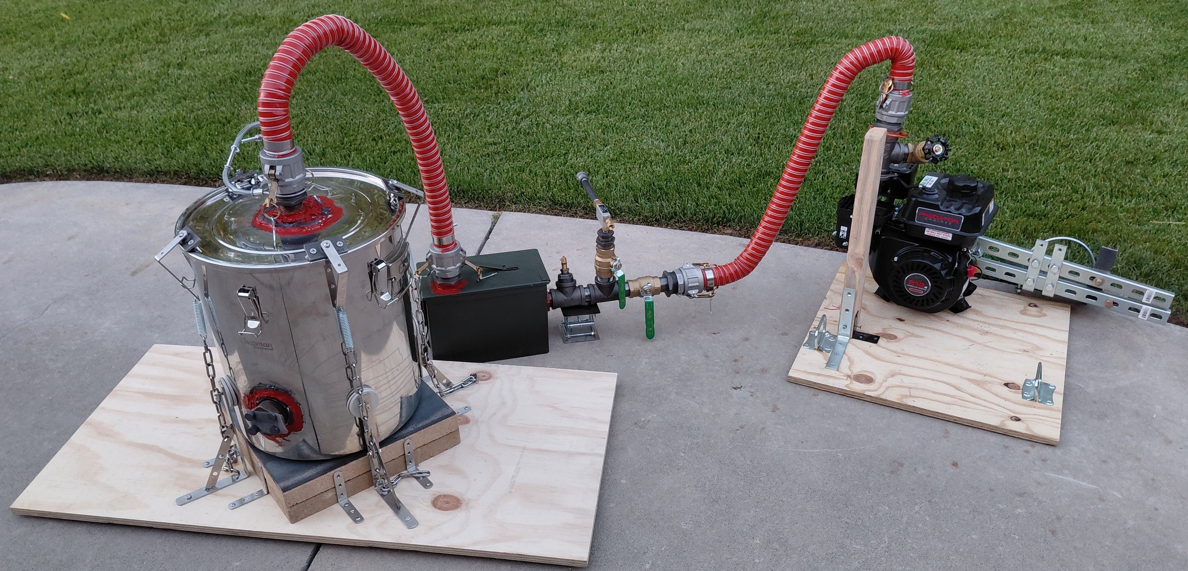
From left to right, a 20 gauge stainless steel, 14 gallon fermenting vessel with a high temperature silicone seal in the lid, modified to follow the Gary Gilmore updraft charcoal reactor plans, connected by wire reinforced silicone hoses to a filter box based on the Matt Ryder design. The filter box also has my attempt at a flare stack with an inline Venturi vacuum pump for startup. The Venturi is driven by a DC powered tire inflator (not pictured). From there, more silicone hose connects to a stationary 212 cc OHV motor sitting on engine mounts, with a setup to mount a truck alternator to the engine housing using electrician’s strut, that I could drive with a belt. (Alternator not pictured, as well as a big air filter that’s usually on the choke intake).
For one thing, real dumb question, but with my hosing and the air filter box, is that likely sufficient to cool down the gas enough below the autoignition point by the time I reach my flare stack ball valve and engine ball valve? Any other advice on what to do and not do when I crack one of those valves and my gas starts mixing with the air in the lines? Also, I saw on this forum that Wayne Baker thought his extra large puff event was caused by too narrow piping; is the consensus that this increases the risk of flashback, and if so could that be a problem with the 3/8" NPT pipe I’m currently using to run my flare out horizontally?
I’m attempting to do everything No Weld, and I’ve leak tested with soapy water, using the exhaust from a shop vac blower to pressurize the system. I do observe a small leak where the bulkhead fitting at the reactor’s intake penetrates the wall of the fermenting vessel. I’ll patch that over with more RTV anyway, but to check my reasoning, do I have it right that since that area is close to where the combustion lobe will be, any small leak of air is likely to get consumed instead of building up a combustible air-fuel mixture?
Obviously I’m only ever going to try running this system outdoors, and I will wear a 1 ppm carbon monoxide detector with an alarm.
I’m using black iron or stainless pretty much everywhere in the system, since I don’t have great intuition for which parts will get hot enough to boil off galvanized zinc. The major exception is the water heater flange in the ammo can that the primary filter material is stretched over, which is either aluminum or galvanized, and is sprayed over with high temp automotive paint.
Learning to make my own charcoal is on the list, but for a first fire attempt I thought I would use some Royal Oak charcoal pellets, advertised as 100% hardwood charcoal. The pellets are ¼" in diameter, and range from ¼" to ¾" long.
Below the next three pictures I have more detail on each system element, for anyone who might be interested. I wrote way, way too much, but anyways it helped me think deeper about the design. I am definitely not expecting anyone to read through everything below, but again any comments on any part of it would be appreciated.
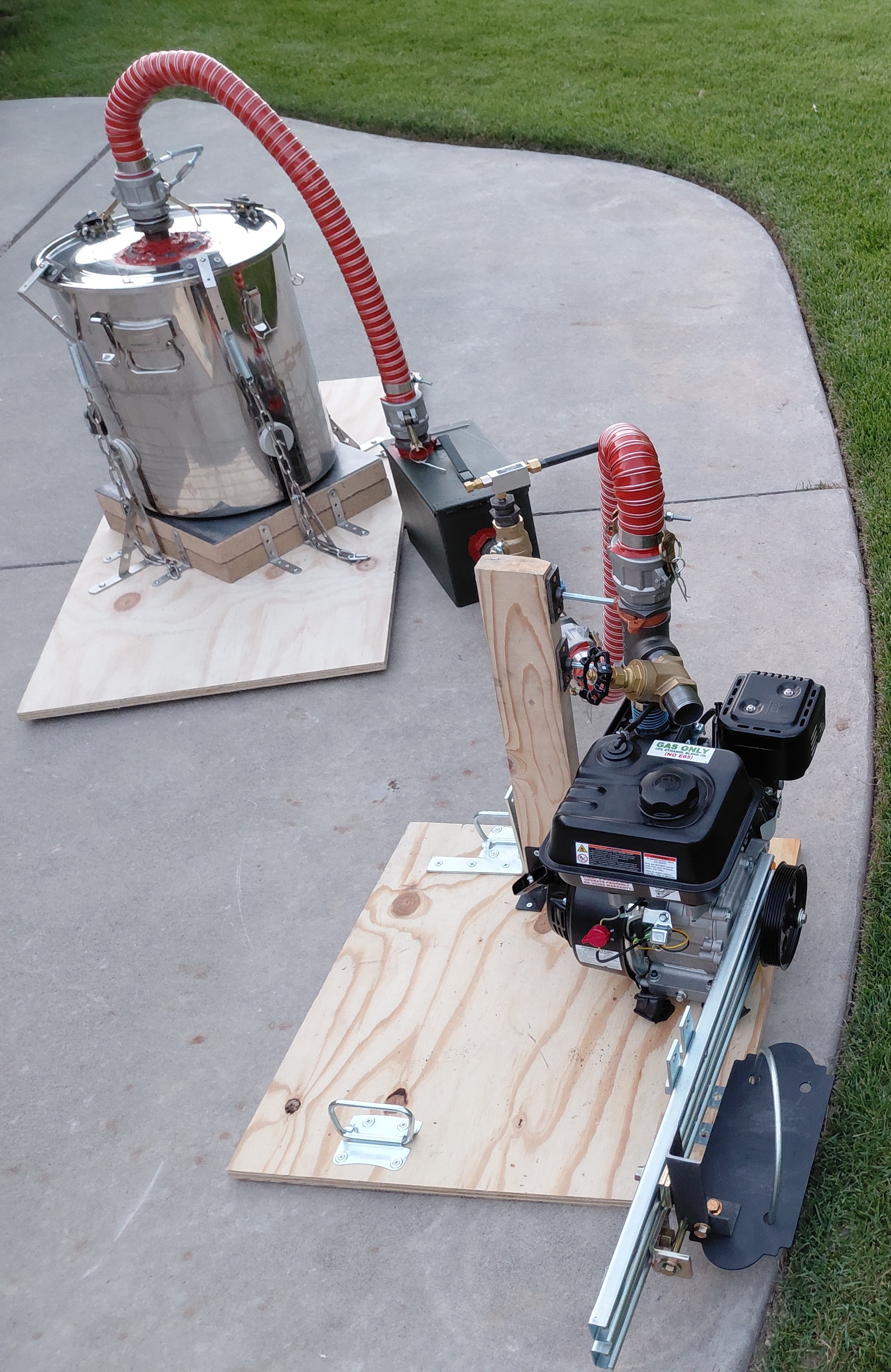
Simple-Fire Updraft Reactor
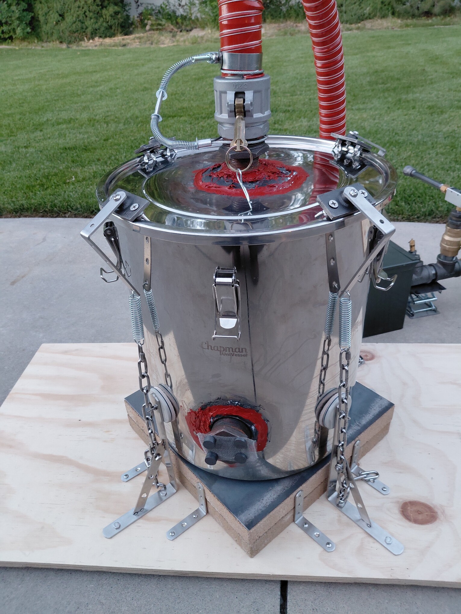
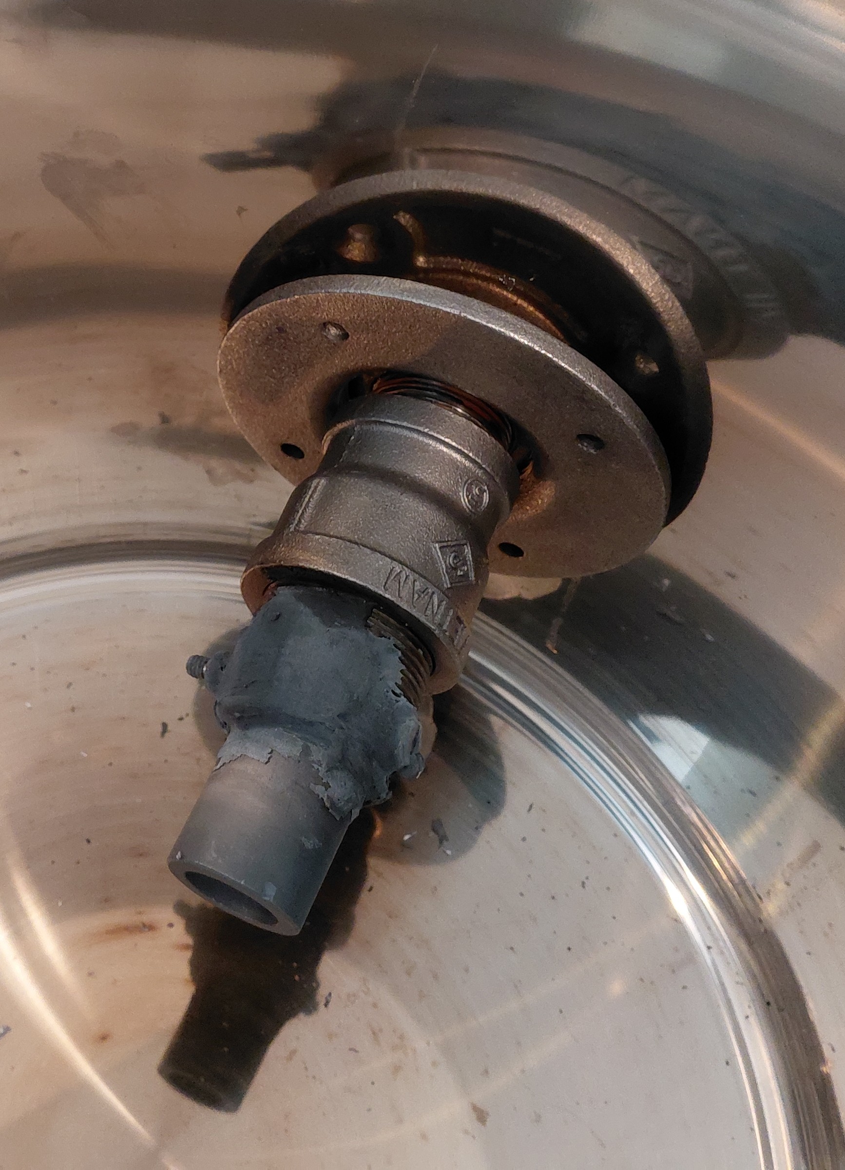
As I mentioned, I’m trying to do this system No Weld. I later saw people who warned that it would be too brittle, but I had already had the big idea to use furnace cement as the first layer of a seal around the penetrations for the reactor intake and outlet, the idea being that I’d read people say that RTV silicone can vaporize from the heat of the reactor, travel through the system, deposit on the working surfaces of an engine and eventually throw a piston or otherwise wreck the motor. So the furnace cement would both provide some insulation for RTV silicone being applied over the cement to make the final seal, and by filling most of the gaps maybe limit the amount of vaporized silicone RTV actually getting sucked in. Everywhere that furnace cement was used, I fired the cement with a heat gun. I’ve since seen for myself just how brittle the furnace cement is, but I’m hoping that I might get away with it for a stationary engine system that will at most be transported from place to place in the bed of a truck (but not used to operate a moving vehicle). Again, any thoughts on this would be great.
My intake jet is a single Hexoloy nozzle, as suggested by Cody Edison Tate and others. The nozzle is mounted in a bulkhead fitting, another suggestion from the forum. To hold it in a NPT pipe fitting, I doubled up a couple of hacksaw blades back to back on a hacksaw, and cut a thick notch in one end of a pipe nipple to make a fork. Then I drilled a hole through both halves of the forked part, near the base of the notch, and ran a screw and bolt through that to make a third class lever that turns the fork into a clamp. The clamp doesn’t have much travel, so I use stainless steel washers beat to fit the curvature as spacers between the Hexoloy and the inside of the pipe nipple, and now I get a little mechanical grab on the hexoloy nozzle. And then I sealed the remaining gaps between the pipe nipple and the Hexoloy with furnace cement, which I’m hoping may also help hold it in mechanically. The nozzle is sloped down a bit, so I have the option to add a water drip later. As a spark arrestor, the intake is screened with stainless steel mesh held on by regular ceramic kitchen magnets, which I hope will stand up to the heat. There’s also stainless mesh tacked to the bottom of the lid at the outlet with more furnace cement, to try to keep stuff from getting launched out through the reactor outlet in the event of a small puff.
The reactor is sitting on what started out as a transport mount. But after I stumbled across Wayne Baker’s post here:
…where his reactor ended up on the roof of his barn, I decided I wanted a puffer lid, instead of just using the locking clamps built into the body of the fermenting vessel. What I’m doing here is using four “grapnels” that grab onto the lip of the lid. Each grapnel is connected to a spring tied by a chain to a bracket on the transport mount, holding the lid down. I can latch each individual grapnel to the lid with one hand, but once they’re all on I can’t lift the lid away from the body of the vessel at all, even with both hands. However, with these puffer lid “grapnels” on, I notice that when I pressurize the reactor with my shop vac blower, (maybe ~1 psi positive pressure, back of envelope?) that’s enough to crack the lid up by maybe a couple of millimeters to vent. Can anyone recommend a rule of thumb on how tight is tight enough for a puffer lid? If it’s not tight enough, I wonder if I’m just making myself more vulnerable to air leaks this way.
Since in the current design I would try operating sitting in the transport mount to have something to tie my puffer lid to, I have the reactor sitting on 3 inches of patio brick and maybe some rockwool, which I hope would be enough to keep the wooden base of the mount from scorching from an hour or so of continuous operation. The transport mount brackets have felt furniture pad bumpers to try and keep the thin gauge stainless of the reactor vessel from getting smashed up during transport, but those probably won’t hold up to heat and I would swap them out with rockwool bumpers for operation. And I was also thinking of staking down the base of the transport mount, to make sure it stays steady in the event of a big puff.
Filter box + Flare Stack
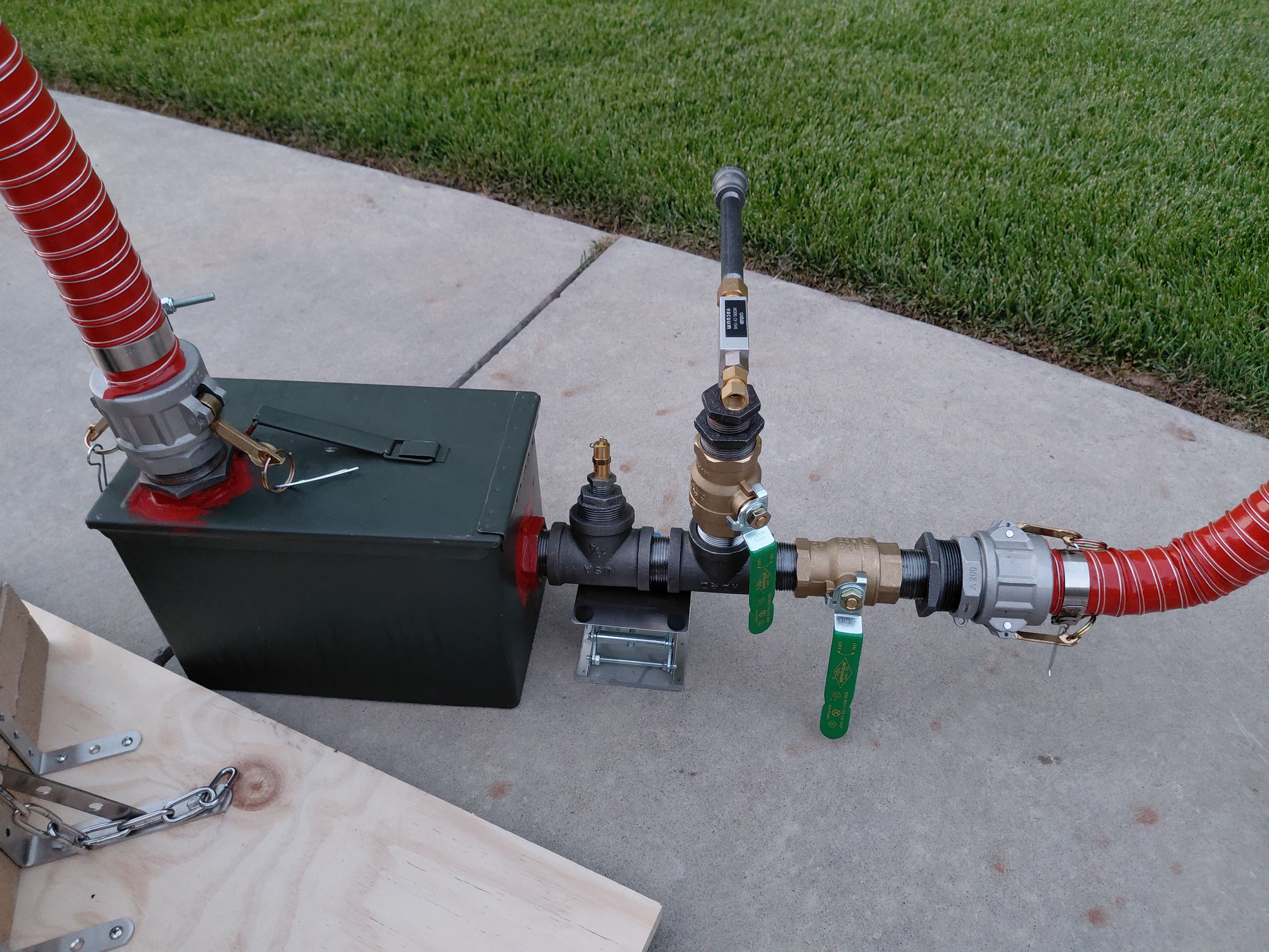
I’m using silicone RTV hose with aluminum cam and groove (camlock) fittings to connect the reactor outlet to an ammo can filter box; both the use of camlocks and the filter box itself is inspired by @Matt Ryder’s ammo can gasifier. Also based on Matt’s design, I’m thinking of leaving the cam and groove locks loose on the reactor and filter box intake ends, to act as a poor man’s safety valve, with whip checks to provide some protection from hose whiplash in case of a flashback. The primary filter is something like 5 micron aquarium filter stretched over a water heater flange bonded to the inside of the ammo can with high heat JB weld. The secondary filter is small animal bedding (think hamster cage) advertised to be 100% pine shavings. Penetrations in the ammo can are sealed only with RTV silicone, no furnace cement, because I guessed that temperatures would be low enough here that the RTV wouldn’t boil off much.
All the stuff hanging off the outlet of the ammo can is a 5 psi re-settable safety valve followed by what is supposed to be a flare stack with an inline venturi vacuum pump for startup, driven by a big DC powered tire inflator (not pictured). My first attempt at making a venturi pump from hardware store fittings had very little suction. I bought a commercial venturi pump that looked like it would work based of its advertised rating, and it gets decent vacuum at its own intake port, but when I connect it to the reactor through the filter box, I’m barely getting enough vacuum to hold a sheet of paper against the reactor intake. Leak testing and moving to a bigger tire inflator didn’t seem to make much difference, and I’m wondering if my aquarium filter material is just too fine for the venturi to draw through, or maybe something else is going on? When I use my shop vac to push blower air through the filter box from intake to outlet, at least by feel I get most of the pressure at the outlet that was going in the intake. Either way, do I understand that I could fall back to pull-starting the system via the starter cord on my stationary engine?
I’m using two gas rated ball valves to connect to or isolate the reactor from the flare stack + venturi and the engine, respectively. Maybe not hot wood gas rated ball valves, though. More silicone RTV hose connects the filter box to the stationary engine. Since I’m expecting more vibration here, I figure I would actually lock both of the camlock fittings on this side, and that’s why I added that 5 psi safety valve, since I’m not relying on the hose just popping off on this side if things get exciting. And also maybe more garden stakes to constrain where the air filter box could go, just in case.
Stationary Engine Assembly
The 212 cc OHV stationary engine is mounted to a wooden base with rubber engine mounts, with a gate valve as a choke. I’m using a 2x4 as a stand to hold the choke and the camlock fitting in place relative to the engine. Pool hose runs from the gate valve choke to the engine’s air filter box intake, just above the engine’s built in-choke and throttle. The pool hose is mounted with hose clamps. There’s an air filter that goes on the gate valve choke. And there’s an arrangement that is supposed to hold a truck alternator on a sliding bed plate that runs on electrician’s strut used as rails that are bolted to the engine chassis, with a bolt that pulls on the bed plate/alternator assembly to tension a serpentine pulley, and another bolt to lock that assembly in place once the belt is tensioned properly. I think my mechanical design for the engine assembly is one of the weaker parts of the whole system, but at this point I want to see if I can actually produce decent gas and get the engine to turn over before I fuss more with the engine mechanical assembly.
If you’ve read this far, thank you for your time. Again, any warnings or suggestions would be appreciated.