I remember reading that a crossdraft will not make engine grader gas on wood.
But I wonder why?
If we have a crossdraft system near the bottom of a cylinder then the all the tar and stuff most to go through the reduction zone where the redhot coal will “clean” it?
My amateur opinion is that the trouble would be with organizing the “flow” of wood chunks so that the wood comes in only on the nozzle side, and there is always a solid bed of glowing charcoal on the gas exit side. Some kind of “shelf” would have to be used, and even then the best I could imagine would be an angled downward flow, otherwise tars and oxygen will certainly bypass the glowing char. And considering the added complexity and the drawbacks, what is the advantage to make such a system worthwhile?
The cross draft maybe the next evolution if designed to handle flows. The problem with a cross draft is the fuel will settle creating openings for the gas to bypass. I think if you stepped the processes you maybe able to overcome that issue. The cross draft design would alleviate packing at any stage of process. It would actually flow much better than a straight down draft.
I think maybe a hybrid where you have a down draft reactor / Hearth that would dead end to a second chamber to start a diagonal reduction zone might work. I would enter a second stage oxidation zone here, (Think Simple Fire Nozzle here). So basically the upper section is your primary Pyrolysis process. The chamber bellow is sort of like an after burner where it is burning off the dirty gases while oxidizing the charcoal produced. Theoretically it will produce much cleaner char gas as the dirty tar gas will most be burned off. any left over the reduction will take care of as it will be hotter.
I do plan to test a down draft version of this where we enter that second stage right at the restriction. Then the next step is to build this stagerd cross draft. The idea here for me is to fit this in the trunk of a car.
A bit of geometry: Spiraling periphery down, spiraling center up.
Learn from a propeller geometry: Radius affects angle… add periphery length and center “length”… to get the principal flow equals …
Balancing nozzle groups… up-blasting ~1,5 times down-blasting for starts… downblasting rules the axial rotation “RPM”… like high pitch screw windings…
This doesnt look like it has a reduction process. This is basically how a rocket stove works. it will not refine the pyrolysis gas down to the simpler chains or create a water shift to H2.
Hi Jim,
Go to the Small engines section on DOW and check out,
“My first small engine run”, to check how I handled the ash
output from my cyclone mounting. This segment shows
actual results of the collection and dumping of the collected
ash and how important and necessary the handling of ash is.
If you have any questions, please don’t hesitate to pick my brain.
Pepe
Your reduction needs to be 4 to 6 times possibly even greater of the volume of your core combustion stage. This heavily determined by fuel though, you have to factor fuel energy density verses the char ash density and available surface area for reaction processes.
So if we say you are using pellet fuel, this fuel pr volume is much higher energy dense than the say wood chips. So your combustion stage will be much smaller to produce the same volume of produced gas. Now your reduction process must be able to match this volume in order to fully process the gas. Too small of reduction will result in weak incomplete processed gas. The reduction also needs to be large enough to handle oscillating flows. In the event fuel hangs up at the hearth level, you can burn down some of the reduction with out completely burning out. However char density is not linear between fuels. Pellets produce a very dense char bed where as chips are very loose pr volume.
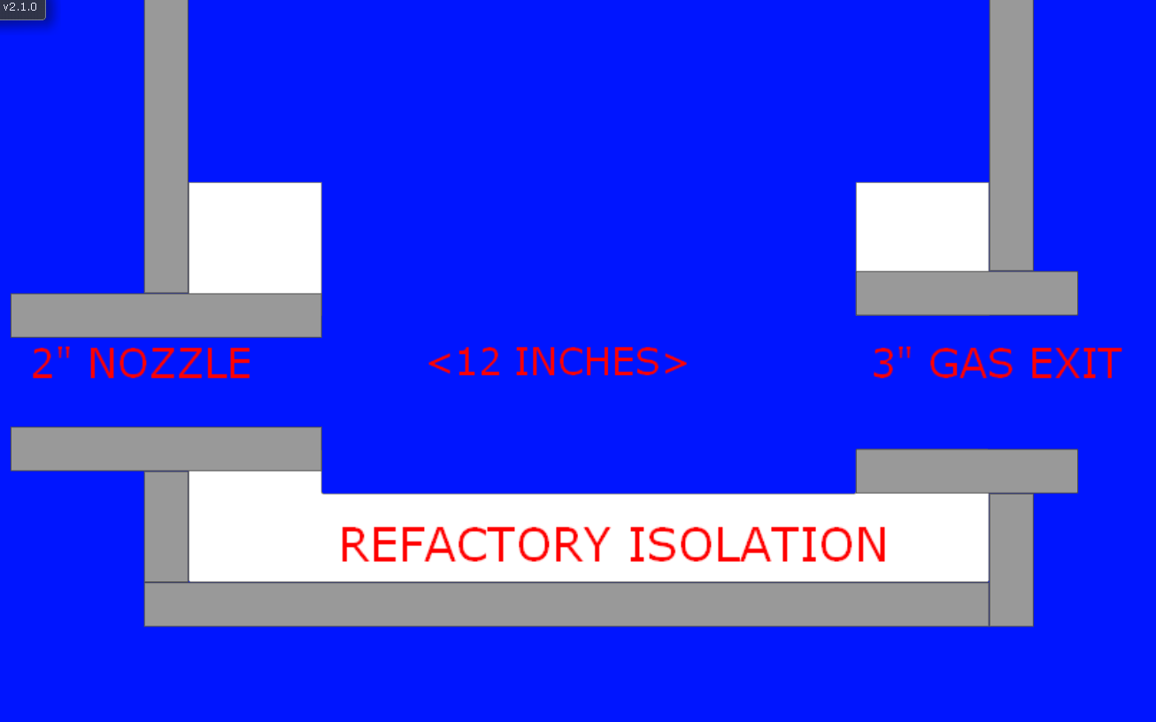
As Matt says, you have put yourself in a bad position; also Matt has put forward a bit of remedy:
To move the intake (air)nozzle a bit upward to get some downward flow of the char.
Otherwise you cannot get char from the air-nozzle side to “voluntarily” flow toward the output.
To avoid “fresh” wood settling in front of the outlet, you have to
establish a “valve” (vault) from the outlet-side to 1/3 diameter of the bucket from the nozzle-side.
Put 3 – 4 nozzles in parallel instead of one; otherwise fresh fuel will bypass a single nozzle (as seen from above) along the “nozzle sector” of the bucket.
Seen horizontally, the nozzle beams should aim just under the edge of the vault, to exclude creeping pyrolyse gases to “join the party”!..
Hope you remember, that “the cold in” air is~ 60% of the cold out gas…
Just for nozzle measurement and velocity calculations…
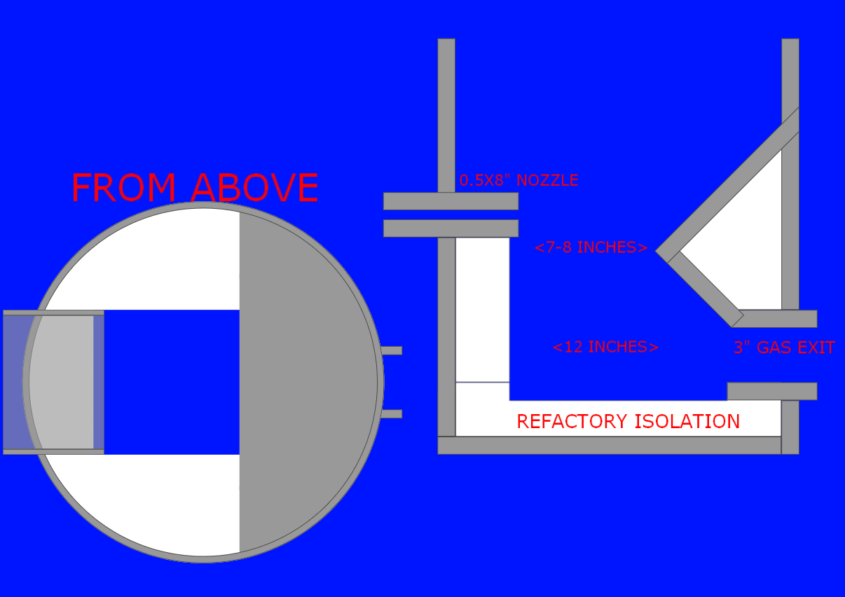
One could probably put the intake nozzle at the same side as the exit as a counterflow or U flow gasifier, wich may make it easier to preheat the intake air?
Like this.
You can not build a better system than the Imbert Gasifier. Is there a false stigma preventing you from building this? Or do you think it is too complicated? I dont understand why everyone is trying to re invent the gasifier.
This is like trying to re invent the Reciprocating Piston Engine. You can certainly build a reciprocating engine at many technology levels. Could build a steam engine, sterling engine, ICE, etc. But at the end of the day its still a reciprocating engine and with out these basic principles in place you wont have a successful working engine.
A gasifier is no different you must include all working principles and processes in order for an engine grade gasifier to work. What you have there is far more complicated than just building a simple Imbert with a Jet array with restriction.
Probably just brainstorming mostly to be hornest.
I realy like the concept of stupid simple and want to find the simplest solution both in construction and how the machinery works.
And a crossdraft can’t get much simple one inlet and one outlet inside a cylinder, just have to get it working.
But when I get to that point it may be more complicated then a Imbert…
I have all parts for a Imbert so I may just build it instead…
You are very much like myself. I also started in this and instantly wanted to invent my own system. Then this mean guy >:( on a forum yelled at me and told me to build an Imbert!! So thats what I did and then later understood why as I began the long process of learning the process.
Seriously start with a simple Imbert or a Simple Fire. Get an engine running and just have fun. Then start adding your own ingenuity. As for simplicity, you already found it in the Imbert. A working machine for running an engine simply does not get any easier than this.