


some progress with the project, 1 hour test of the briggs engine on chargas…
the sturdy american runs nice even with his not so nice cylinder walls…
no oil smoke till now and clean spark plug- no oil on it…
strong compression to feel at starting…
new design of the start valve and gas hose adapter…both to turn independent in different directions…
and old tire under the motor as vibration damper…works really fine, the whole unit is not roaming…
22 Likes
Giorgio, as always, does everything very thoughtfully, and this generator will also become a very good product,…
Some time ago we already discussed the characteristics of asynchronous and synchronous generators, but let me mention a few of them:
Synchronous generator:
- the winding in the rotor is fed via two rings on which graphite brushes slide, the voltage regulator adjusts the strength of this current, thus changing the density of the magnetic field in the rotating rotor and thus the induced voltage in the stator
- alternating voltage is induced in the stator
- the power used to magnetize the rotor represents approx. 5-10% of the total power
- most car alternators work according to this procedure, they only have a rectifier added, which directs the three-phase AC voltage from the stator to DC
- professional synchronous generators are relatively expensive devices
Asynchronous motor-generator:
- the asynchronous motor is the most common element that is used to drive devices, but at the same time it practically does not need maintenance, due to its very widespread use, the purchase costs are favorable
- if we want to use an asynchronous motor as a generator, it is necessary to maintain the magnetic field in the rotor, this is achieved by adding a capacitor, which is charged with electricity at one moment and emits it back at the next moment,… this enables the maintenance of the magnetic field and operation as a generator
- since the induced voltage depends on the strength of the magnetic field and the speed of movement of this field in relation to the winding, it is best to use a motor with high revolutions (3000/min), thus the reactive currents are the smallest and thus also the heat losses
- if we use an asynchronous motor with a capacitor as a generator and do not regulate the voltage level, we only maintain the number of revolutions, the voltage changes according to the load, well, this still allows a good supply of undemanding consumers with electricity
-consumers that do not have a large inductive character (electric heaters, collector electric motors - motors with brushes (electric chain saw, angle cutter, hand drills,…), inverter welding machine) work well with this generator - inductive consumers (asynchronous motors, transformers, welding transformers,…) work worse, because with their inductive nature they destroy the stable maintenance of the magnetization of the rotor
Since I am using an asynchronous generator and want a stable voltage, I will do the following:
- installed a rectifier on all three phases, so I will get DC voltage, which will be supplied evenly from all three phases, this DC electricity can be directly used for the needs of collector motors (electric saw), inverter welding machines, heaters
- for the needs of inductive consumers, a three-phase inverter will serve, which will additionally be connected to the three-phase socket from the generator
16 Likes
Thanks Tone, but cant follow this one. What kind of a inverter do you plan to use?
7 Likes
Tone, this used to be my speciallity in school, but 40 years past since then and there were many distractions at that age. How does loading down only one phase affect things? An angle grinder for example.
6 Likes

I want to add some details here.
When you go to add the capacitors to your motor, lay them out on a plank or table and arrange them in the same configuration as the motor windings. So if the motor is a delta, the lay the capacitors out in a triangle. If it’s a star, the lay them out in a “Y” shape. This make keeping track of which connection goes where, a lot easier.
Wire the motor coils in parallel with the capacitor. One coil for one capacitor.
Use motor run capacitors, not motor start capacitors.
Cut out the bleed down resistor if the capacitor has it.
To initiate the capacitor/motor, start it spinning and touch 12vdc to one of the capacitors.
Use high voltage capacitors. Ex. If the motor was a 220vac motor, then use 440vac motor run capacitors.
As far as the legs, if you are spinning a 12hp motor, and you only are using one leg, then you will only get a little bit less then 4hp out of that leg. The balance won’t matter, but it is criminal to waste the power, so do some washing, or water pumping.
These motors work best as generators when the load is constant, and the capacitors are adjusted to match the voltage and frequency.
Remember capacitors can be connected in parallel or series to adjust the capacitance. It’s opposite of resistors tho. So capacitors in series decrease capacitance, while capacitors in parallel add capacitance.
Other details:
Those big horse power three phase motors have configurable windings, so they have multiple coils on one leg, whose ends are brought out, to a connection box. Always draw out a diagram to keep track of these connections, they can be very confusing.
14 Likes
it is clear, in this - for me- complicated field…tone is my mentor…
otherwise i would combine damages…
8 Likes
Here in Europe, we have asynchronous motors of higher power built to operate at an interphase voltage of 3x400V, so each winding is designed for a voltage of 400V, so if we use this motor as a generator and connect it in a star, a very high voltage of approx. 700V will appear at the connection, so we have to tie it in a triangle. Since we also want to get out the phase voltage of 230 V, we need a zero, which the triangle connection does not provide, so we connect the capacitors in a star and there is a zero in the center of this connection. When the motor rotates, voltage soon appears, without external excitation.
When we load one phase, the voltage on this phase decreases, while on the other two it increases, which means that zero moves from the center. An increase in the voltage on the unloaded phases also causes a higher voltage on the capacitors, which “magnetize” the rotor more intensively,… so we get an interesting amount of power out of one phase (probably more than half of the motor’s rated power), this phenomenon is not present with a synchronous generator only a third of the rated power.
Here I must warn you that you should not connect small consumers to the unloaded phases, because they will burn out due to a high voltage surge.
“off grid” solar inverters have the option of connecting a generator, or several DC inputs, but if a DC input were to be used, it would be necessary to install a three-phase rectifier.
11 Likes
Tone, I am very interested in seeing the DC circuitry you use in conjunction the motor. It sounds like the answer to the wild voltage swings when the motor is unloaded.
One comment that I failed to mention is money. If someone is here in the US, trying to use this type of generator, they have to be really, incredibly, low on funds. I know, I was when I was messing around with them. In fact, I traded my 15hp 440vac three phase motor for a 6000watt Lister/Petter diesel generator.
All the more reason to see the DC addition Tone mentioned, and see what kind of junk it can be built with.
9 Likes
I think it is very easy with a bridge rectifier and off the shelve solar inverter. But first I have to test that in real live. Waiting for capacitors. No need to guard the rpm with a grid tied system then.
Thanks Tone
8 Likes
I can see getting the diodes for the bridge from junk microwaves, but where do you get a buck converter (DC to DC converter) to go from ~220 vdc down to 12vdc.
5 Likes
No, solar inverter works fine with 300 or 400 VDC. Bridge is a few dollars. Cant get easier or cheaper and you get a pure sine
5 Likes
Your constraints don’t include being broke, which is the only reason one would want to do this.
That aside, what kind of inverter takes 400vdc? I would like to study the specs. The highest voltage inverter I have seen here is 48vdc. Point me in the right direction, sounds like I am learning. ![]()
7 Likes
Do you mean something like this?
Solar Drive Inverter Variable Frequency Drive DC 400V to 700V Variable Frequency Input for Electrical Testing AC 3Ph 0-380V 0-650Hz Output Amazon.com
4 Likes
You seem pretty fond of old stuff Bruce. If you ever get around TC and want an old Hobart 440V welder I have one I’ll give you. Look similar to the ones pictured in this link. Got dumped off here by one of my sons and I have no use for it.
10 Likes
I am hoping to build one of these motor generators soon and will hope you experts here can guide me and talk me through it , i will find a motor first and go on from there reading what Tone said i should be looking for at least a 3000 rpm motor lets see what i can find .
Dave
6 Likes
actually i am using generator with cheap solar MPPT battery charger (PowerMr) to charge 48v battery bank.
for most time it works fine, but sometimes MPPT gets confused by generator output and disconnects.
sometimes it takes a couple minutes of fiddling with engine RPMs to get it back online - pretty annoying.
also i suspect the alternator (car type) is part of the problem as its rotor current is dependent on load
and gives weird feedback to MPPT.
10 Likes
I used a Yanmar clone with a 4 kW motor, ran it 3050 rpm so just a little above 50 Hz. Rpm is critical this way but it works really well. With capacitors and a bridge rectifier this setup will deliver DC. About the same range as solar panels do. Changed my roof once again and there are some Growatts doing nothing. The plan is just to hook them up. Still a liitle scared, high voltage dc is really deadly. My polski collegea that fixed most of my panels got 500 V Dc once, couldnt lift anything for a week. He was lucky that the current was in his finger , not though the body…
So, the same setup as Andis but with asynchrone motor, capacitors (thanks Tone) and bridge rectifier. Not poor man setup but very cool grid tide or off grid pure sine setup the easy/simple way.
6 Likes
Hi Joep i am hoping to do the same with my Yanmar L100 clone engines i have i , would love to see some photo’s of yours when you have time .
That would work great for me as i also have some grid tie and hybrid inverters love to be able to do that .
Dave
6 Likes
How are you converting the AC output of the alternator to DC?
There is also a thermistor on the alternator that will disengage it if it gets too hot. They are wax, they melt, and need to solidify before becoming operational again. And a car alternator is depending on airflow from the fan or from the vehicle speed to help stay cool. You can measure the temp with the infrared temperature thermometer gun. to see if that might be an issue. It takes a few minutes for the all the metal inside the alternator to cool off. If that is an issue a fan would help it and/or some heat sinks to add cooling fins.
Because the output is most likely not constant after the conversion, if the mppt polls and hits the high point, then it tries to increase the voltage yet again, it might pull too much. so if you look at this picture, and yours looks a little different but you see there is a ripple in C which is even after the filter which is going to try to get the alternator to try and draw even more power which the alternator can’t handle for any length of time.
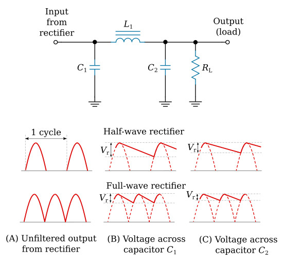
This is the actual page I swiped the photo from, but it mostly about figuring out the capacitors to build the smoothing circuit. Pictures are easier to understand. ![]()
6 Likes
I think we have the same.

4 Likes