New downdraft, charcoal motorcycle build- need insight!

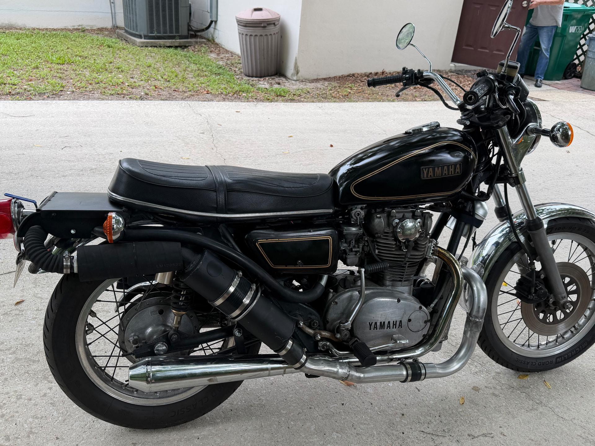
In late 2024, following the high obtained by building WK gasifier, I became obsessed with the idea of gasifying an older, somewhat large displacement motorcycle.

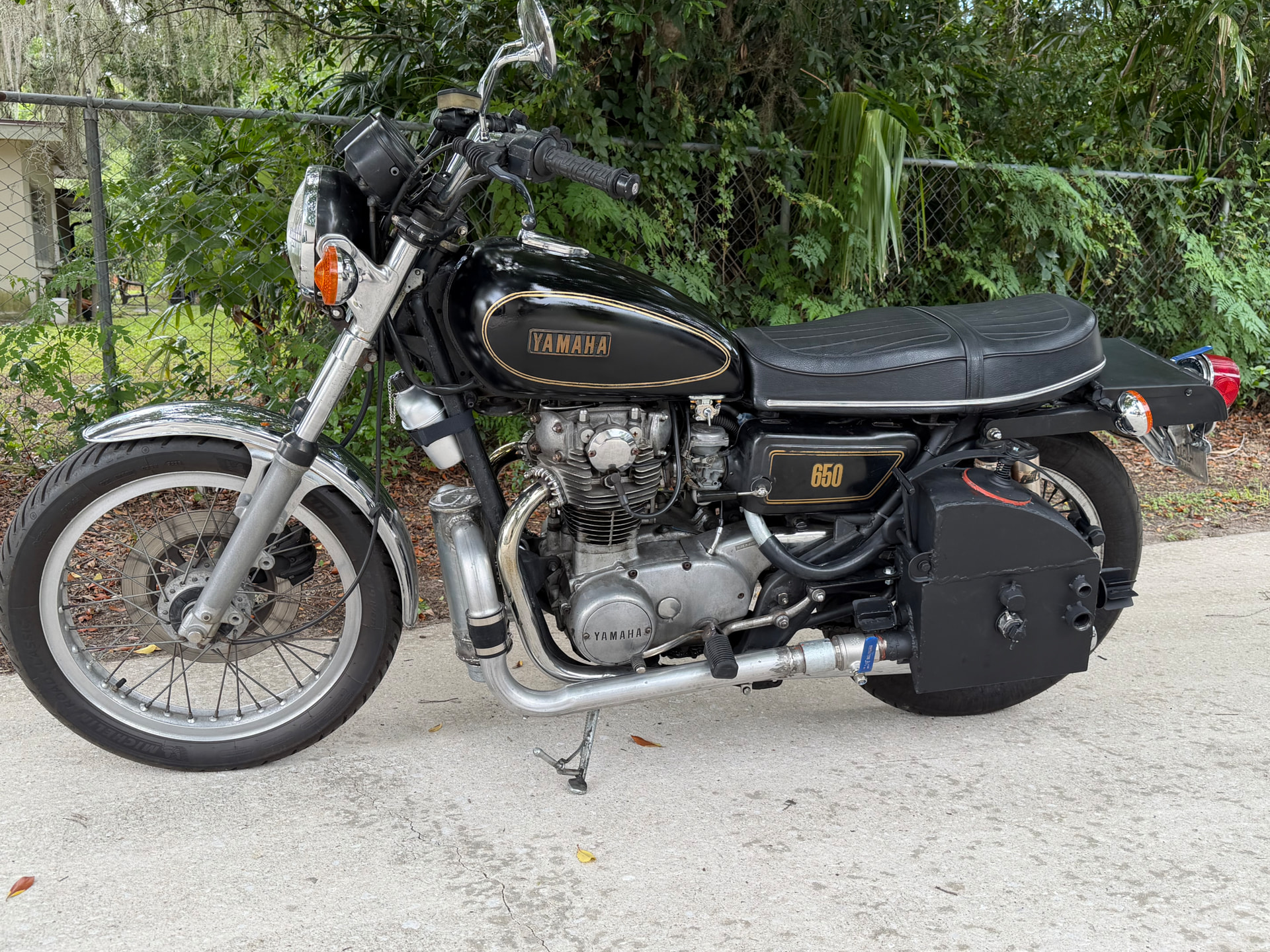
What I ended up with wasn’t one of the original bikes I was looking for, but it was a fairly collectible bike at a great price.

The main goal for me was to make a compact build, which was reversible, so I could unbolt the entire unit quickly—and bring it back to bone stock again.

I’ve been calling this project—“Charmaha”.

It’s been sitting in the garage for a year. About 4 months ago I began working on it.

The good news: it’s finished!

The bad news: I can’t get it to run on chargas— can’t even get it to flare.:pensive_face:

So far:

After filling up with charcoal, the gas outlet valve at the bottom left of the reactor gets opened.

With the air inlet port (lower middle cap) opened, the charcoal gets lit by a torch through the lighting port, (smaller cap just above the air inlet).

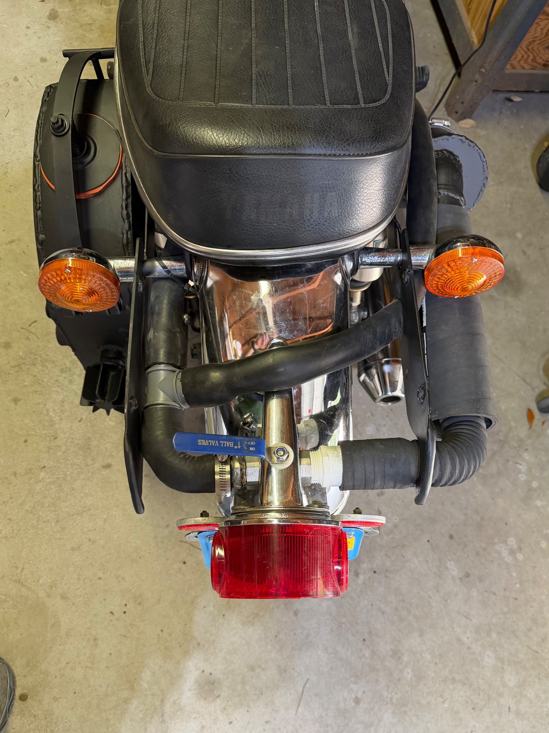
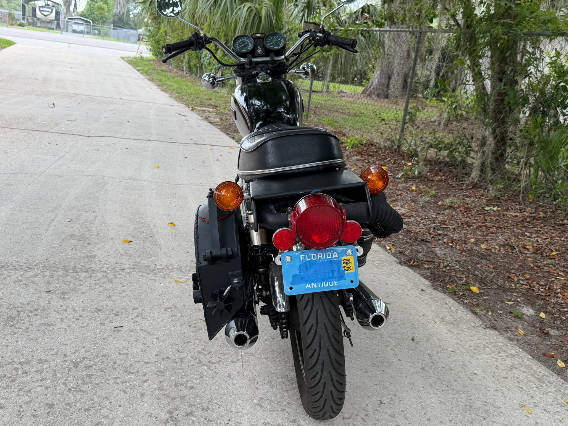
The valve that sits on top of the tail light mount gets closed and a flare pipe is inserted in the system near the end of the blower.

The blower gets turned on, and I let it run for several minutes. I crank up the engine so the blower doesn’t run the old battery down.

At this point, I’ve been trying to light whatever gas is coming out of the flare pipe.

No luck.

I’ve tried removing the flare pipe and returning the plumbing to what should be the normal running state, ie. whatever chargas is produced can be sucked towards the carburetors.

Then, I ride away, running on gasoline, turn my fuel petcock off— (no gasoline going to the carbs), and close the AFR valve with high hopes that any chargas produced can be sucked towards the carbs, by the engine vacuum.

As you would expect it runs wonderfully for about two minutes, until the carb bowls run out of fuel. Then it’s hard to tell if the sputtering is just the bike running out of gas (most likely), or running poorly on char gas, as I fiddle with opening the AFR valve some. But— it eventually dies completely.

Included are some pictures if anyone cares to help with the diagnosis.

My first thoughts:

-Air leaks are weakening the char-gas, (quite possible).

-The 2" diameter bilge blower has too little suction.

-The 2" exhaust pipes used for cooling the gas are just too big, so it just might take a lot more time to displace all the air and fill this up with charge gas.

-The charcoal inside the reactor is not staying lit (not enough air inlet?)

Yet the unit feels hot in the nozzle area—even though the bottom half is insulated.

-The entire reactor is just too compact (not enough chargas produced to power a 650cc twin).

-the nozzle holes (facing upward) are plugged with unlit charcoal restricting the air— I just thought of this one, this could be it!

-it’s just plain built wrong (very possible-even likely ), as I tried to incorporate good ideas from others into this, but not sure if I incorporated them correctly.

-All or a combination of the above.

Here are a few other particulars :

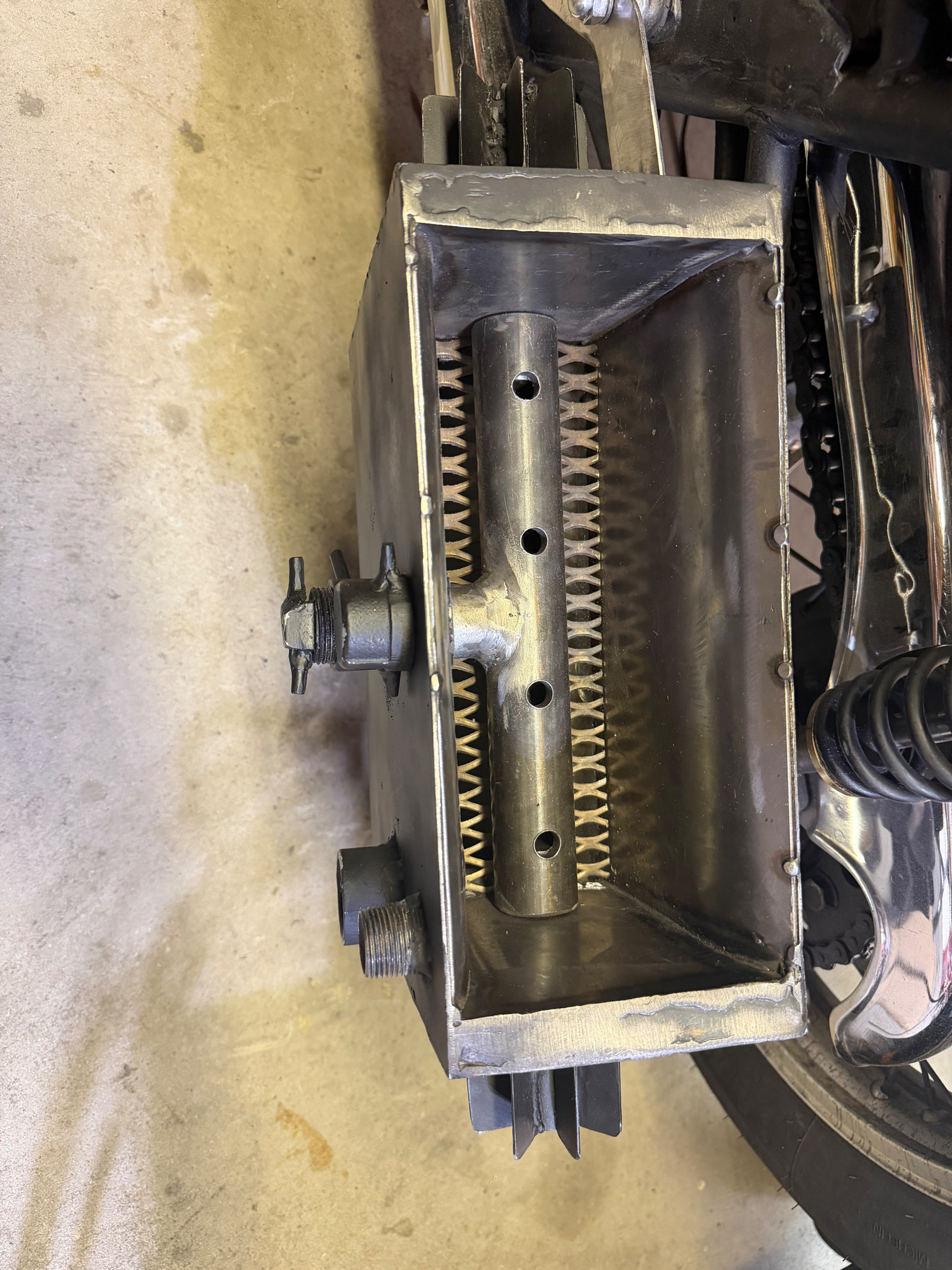
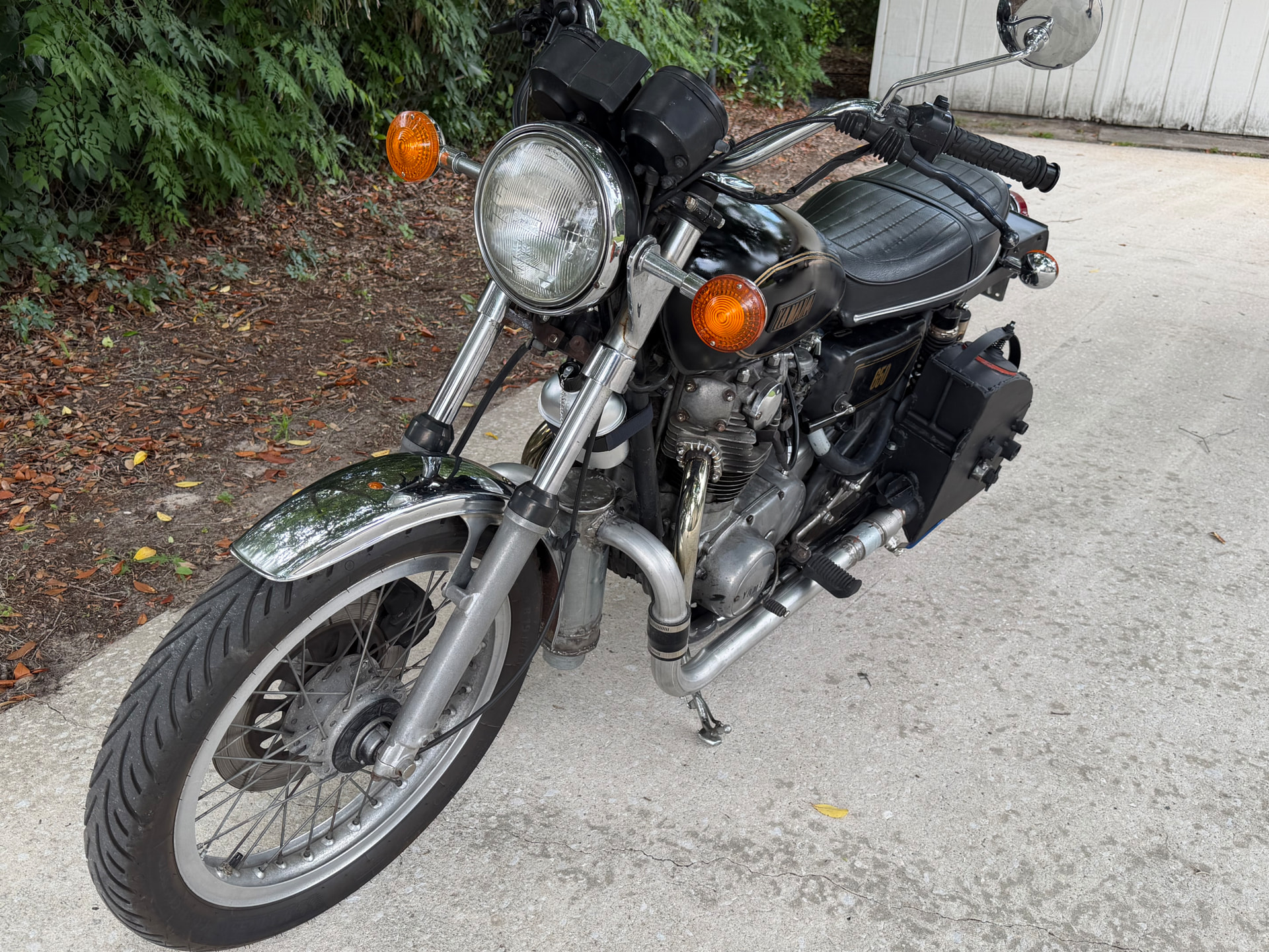
It has a Lettinger style nozzle with 4 holes (each approx. 1/2" diameter.)

It is a TEE shaped nozzle, with air coming in from the middle of the side and then turns toward both ends length wise.

The nozzle sits on a stainless steel grate, with a few inches for ash collection below it. There are some solid 1 inch rods that are for dissipating heat to the outside-(you can see the fins on the reactor).

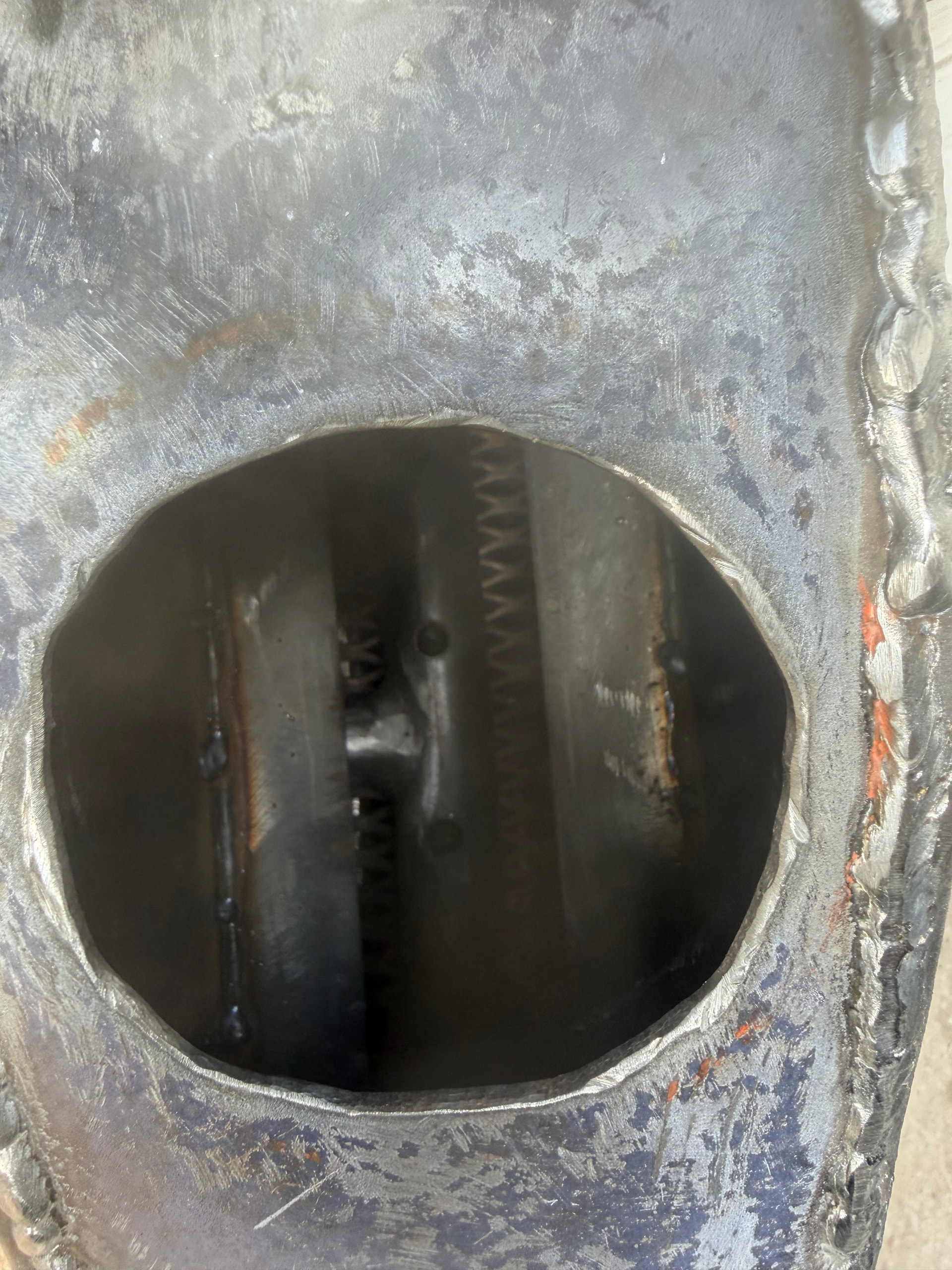
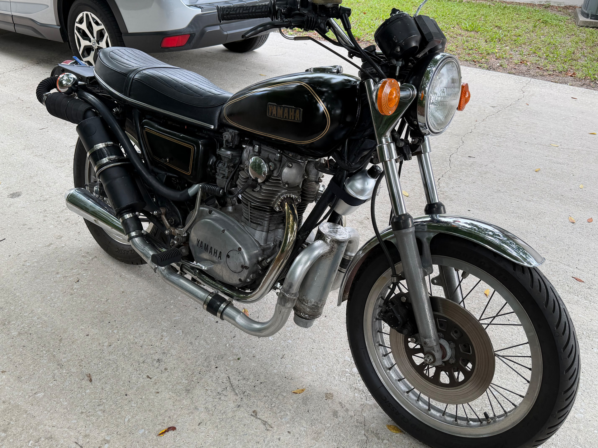
The cylinder sitting between the two front down tubes is a dropbox. It has a vertical plate welded from the top to about 3/4 of the way down. The incoming gas hits the plate at the top and moves downward and underneath the plate, then exits out of the top of the other side of the plate.

The diagonally arranged cylinder on the right side of the bike is the filter. The top half is foam, the bottom half, pine straw.

From there, the gas exits into the 2 inch blower which is hiding under that giant, short section of radiator hose.

The valve at the tail light controls chargas flow to a wye, beneath the fender rack, and branches to each of the carbs.

There are two mixer boxes that are welded together as a unit and fit onto the dual carbs. On the left side cover is a lever attached to a rod that passes through both mixer boxes and two discs are welded on the rod to act as butterfly valves to to control the AFR for both carbs.

On the right side cover, you can see a little push pull knob that controls the blower.

Whew! So sorry to be this wordy, but I’m trying to help anyone that wants to tackle this with me.

The project has been a lot of fun for me even though it’s not working out ----yet. I’m willing to make major modifications

Thanks

10 Likes

First off i would like to congratulate you on a very stylish and stelfie build its a credit to you .

Now the problem solving issue’s should be starting with only 1 action at a time , do not be tempted to start changing more than 1 thing at a time , so if that was me i would start by blowing back from the output pipe with a small blower and soapy water , unless you have no air leaks it will never run correctly if at all . once you have established there are no air leaks then start by checking the size of your charcoal and the moisture of it before changing anything on the actual gasifier itself .

Your inline fan is it always in the circuit ? can you bypass it ? not a fan of having it in line as it gets sooted up and melts if your gas is too hot , i think its way over size for your build maybe try slowing the fan down .

Anyway good luck let us know how you get on .

Dave

Dave

8 Likes

Thanks, Dave for replying. I also think I should only try one thing at a time; thanks for the reminder.

It does makes sense to rule out the reactor first, I’ll try soaping the outside of the reactor down and blowing into the gas outlet pipe.

As far as the blower, it really doesn’t seem too powerful to me, but it is a small reactor, so maybe it is too much.

I’m using charcoal I made from oak. It is 1/4 to 3/4 of an inch; all of it cubed.

Thanks again for chiming in!

4 Likes

Does it have a series of nozzles or just one? You mentioned an air manifold so I’m assuming it’s at least more than one.

You should at least be getting some sort of a flare, that’s very odd. I wonder if the distance from the nozzle(s) to the gas exit isn’t long enough? Is the gas coming out super hot? When I ran a test with a diagonal downdraft I had maybe a 24" distance from nozzle to exit and 20 feet of a single run of cooling pipe and it was still so hot it melted my filter bag and cooked the neoprene seal of the ammo box filter. Probably had a hot leak in the cooling pipe in my case.

That pannier styled gasifier is very tidy, I like it.

3 Likes

Thanks, Cody,

The air inlet pipe is attached in a T fashion to a common pipe that has a series of holes, pointing upward, (like Kristen Lettinger’s) nozzles. The pipe has four equally spaced holes. I have just been calling them nozzle holes.

I’ll try to find some pictures taken during I the build, to show the arrangement and distances, for clarity.

4 Likes

Actually, this type of nozzle, that I’m calling Leininger style, I believe would also be called a flute nozzle. Only difference is that the air enters into the middle of it and then tees 90° in both directions.

4 Likes

In the second picture, the blower is beneath a large, split section of radiator hose on the right side. It shows the routing of the gas to a “wye”, and then to each carb.

This last picture is looking down from the 5" filler hole.There are 1/4" angle pieces welded on the sides to channel the charcoal into sort of a vertical “lake of fire” burn zone above the nozzle holes.

You may have to zoom in— just don’t zoom in on the welds- ha ha.

4 Likes

The top (curved hopper section) is quarter inch thick all the way around. It was plenty warm after burning for a while, but never got super hot. If I can get this running, I do plan on making an insulated jacket for the top section byriveting some ceramic insulation underneath some leather.

The bottom section where the nozzle is there is 1 inch of ceramic insulation sandwiched tightly in the three-quarter inch space between two walls. Near the top of the bottom section the two walls are pinched together and welded.

3 Likes

Beautiful build. If you remove the grate and fill the area below the grate with charcoal and seal up 3 of the nozzles leaving only the nozzle farthest away from gas outlet, how many inches is the path through charcoal to outlet?

4 Likes

Bruce,

The length of the entire unit is 12 inches. So I would guess, if I left only the nozzle hole furthest from the outlet open, it would be about 11 inches.

Are you thinking maybe the draft should pass through more of a distance of char, moving sideways and downward, that it might be better?

The nozzle can be rotated and pulled out from the top hole, so that could be tried. Though I probably need to just test for leaks in the outside jacket first.

But if that’s what you’re thinking, it sounds very interesting.

4 Likes

How big are those flute holes? They look pretty large. My 350 SBC ran with 3, 5/8" diameter holes as an updraft like a classic Kristijan system.

How hard would it be to maybe tap the jets for pipe plugs and test out Bruce’s theory?

4 Likes

Cody,

Those four holes are each a fraction less than 1/2 inch (my half inch bit was worn slap out).

I might test out Bruce’s theory, but in the next couple days, I’m going to try to do more leak testing by blowing air in the unit with soap all over it.

If I can fix other leaks or hopefully not find any, and it still doesn’t work then maybe I’ll take it off again and try plugging those first three holes.

If nothing else works, do you think I should rework it so that the orientation the of the nozzle holes are not facing up? Should I bring the nozzle up slightly toward the top and turn it over and face it downwards?

3 Likes

I don’t think the upwards direction is necessarily the problem, it’ll still try to find the path of least resistance. I think the upwards jet will help prevent bridging, like how Joni has his raw wood system use 20° upwards facing jets.

Edit: just out of curiosity I checked with Koen’s nozzle spreadsheet and plugged in with a 650cc engine and a 3000 RPM benchmark, 4 nozzles as a rule of thumb according to the spreadsheet should be around 5.5mm. or 11.1mm for a single nozzle.

3 Likes

barry, very nice and steahlt design, looks like boxes for stuff…i think the nozzle holes are too big in diameter, so the air stream cannot speed up enough and therefore you not reach the minimum temperature for the hearth for gas producing…should be over 650 degree celsius, better 800…on my pasquali with a 700ccm engine i have only a single nozzle with about 12 mm diameter than downdraft gasstream with about 20 cm depht from nozzle tip to the grate…reaction area and reduction area is sufficient in this way, good gas and good power…

1 Like

Thanks Cody for checking that.

I also used Koen’s spreadsheet, but was not really sure if I was correct in the way I was using it. So the hole size seems slightly large for the engine size, but maybe too large for the small reactor size?

1 Like

Giorgio,

Thanks for responding. I’ve enjoyed reading several of your posts.

After I rule out/in any leaks on the case, I may begin by plugging off the closest two of the four holes to the outlet and try it again.

1 Like