Both, Then one more for adjusting the air.
Isn’t a vacuum ignition advance canister essentially the same gizmo except it is single action with a spring and adjustment? So you just need two of them? .
(not trying to take away from chris’s project, just more curious at this point.)
One of my Jeeps had larger ones to control the heater/vent flappers. But not as large as Chris’.
Jeff
I think it’s basically the same except a lot smaller and instead of dealing with inches of mercury (engine vacuum strength) your dealing with down to a part of an inch of h2o (difference between incoming gas and air).
Andy
I think in your example it would be
(27 pounds + the force from atmospheric pressure) - (23 pounds + the force from atmospheric pressure) = 4 pounds
The advantage I see to having two diaphragms is not having to deal with the friction loss of going through one of the diaphragm housings an keeping it air tight. I hope something like a linear bearing will take care of that.
Chris, Sorry if I’m butting in to much. I’ve been thinking about this a long time. Can’t wait to see what you do with it 
1 Like
I’ve been thinking about this a long time too Marvin… and I’m with you on the two diaphragms… I’ve even bought some stainless mixing bowls… just haven’t gotten around to building anything. Yup, get’er done Chris… I wanna see it work. (with out doing it myself :))
1 Like
Well I did try doing this winter of 2010-11 in the VictoryGasworks developement shop.
Works on engines above 3 cyclinders with a steady intake vacumn. Sigh. I was trying on single and twin cylinder engines. Pulasting intake makes it unsuable for these. Be warned.
Tricky to fab/design for though.
Yep. Yep. Need at least an 8" (200mm) diameter can set up for the low,l ow pressures involved to be able to make a usable mechanical movement WITH SENSITIVITY. This example is as close as looking at any street gas building pressure regulator/shut off valving!!
Chris is on the right route with his thick rigid end cans. My first sytem end cans out of pie plates flexed too much loosing movement.
My first membranes were too squisky soft unreinfirced then balloning losing again applied movement.
My first center plates wee too small allowing menbrane movement without enough force trasfer to the actuator shaft.
Bigger plates were too heavy as SS steel, or even wood. And my first brass shafts too heavy. Makes for slowed responses. Use Aluminum.
On a dual chamber set up the shaft protusion side has to be movable capable sealed WITHOUT dragging resistance. And Without a bellows type shaft seal putting false centering “spring” throwing off the movement range.
And this lasts are some of the of the advantages of a dual actuator system.
I have all confidence ChrisKY will getter’done. And share his learning.
My evolved system was left with Ben as a VGWShop development. Evne was once videoed.
He chose instead to go with an ALL small engine friendly with electronic O2 feedback system.
Ha! On small engines I just let woodgas mixtures float too rich <=> too lean happy with any variable speed 1000 to 3000 watts shaft capabilty. I DC generate.
Regards
Steve Unruh
6 Likes
Hello, Steve!
You make me mighty surprised! Shure you knew the nature of wobbling sucking waves into a single cylinder motor at the outset! That was hardly any surprise.
Also, you knew, that those waves will travel at equal speed in equal tubes backward from the point where they are dispensed (with twin flaps) together.
Also you must have known that symmetry keeps events proceeding in two ”legs” at the same time.
Sampling times well below the sucking frequency makes both membrane chambers ”equally immune” to the heavy wobbling…
Well, this is not meant to be any kind of personal Inquisition (you know me better than that), but I am stunned by the setup…
I am sure you can get it running perfect, with the right materials!
Do well!
Max
1 Like
You’ve got me wondering M G if you could use two vacuum lines, one a bit longer to delay the pulsation in that one and the two pulses would cancel each other out?
Symmetry is the king! don’t introduce any unsymmetry!
max
Yes MaxG you are correct. Both legs must be equalized to symmetrical conditions to function properly. Later on my own time I did get closer with pulsating engines. The fresh air leg has to be extended to the same distance as the gas supply leg to it’s last gasifier downstream leg restriction point. Usually a final filter. And a fresh air restrictive air filter installed to match the same as the gas filter.
This could be tuned in done on a labor free DIY system.
Not on a for-sale package system to go onto $500 USD consumer engine generator sets. My solution became too expensive versus a works on all electronic solution as BenP’s evolved to shown in his last book.
Yes I was a dumb-dumb, blindsiding myself on the uniqueness of single and twin cylinder engines.
It was not pleasant to have promised and then to fail at a get-together while being videoed.
I should have motorcyle, snowmobile racer tuned in my younger years. Nope. Economy cars tuning. All four cylinders 1098cc to 2600cc. And two of these went very, very, scary fast on river/mountain roads.
Regards
Steve Unruh
1 Like
A real simple way to dampen the pulsing would be to make the membrane chambers large and the suction lines fairly small. This makes for a slower filling time on the membrane.
2 Likes
Ha! Ha!
Just got throuh listening to the first couple of hours of last Fridays chat.
Lots of dicussion on Chris’s Pressure Balance Gas Mix Optimizer there.
Now brother ArvidO I never said it could not be done for single and twin cylinder pulsating intake engines.
Just said it would have to be very fine tuned in for that specific engine; then limiting that engines RPM/load range in my experences Becomes just like a narrow power band “peakie!” usable 2-stroke tuned exhaust system. Dog-dog-dog-WooWOW-ehhh-ehhh Where’s my power go?
Hint: Use internal piping reversed edges circular rigdes to reflect/dampen tampen down the pressure waves. Read about this on a 70’s hot-rod tuned exhaust pipe system. Works. Bugger to fabricate. Progressive pipe in a pipe in a pipe works to make these one way edge-ledges. Sigh. The reversion ridges builds up with soots on woodgas fuel back puffing.
Regards
Steve Unruh
1 Like
Hey brother Steve… never mean to sound like i’m dissing you in anyway… I totally respect you’re knowledge that has come from trying and doing a lot of stuff… I appreciate you’re input greatly.
Just gotta be a way is all… or at least that’s my feelings, not they are always grounded in reality… 
Sooner or later someone (hopefully one of us) is gonna figure it all out.
3 Likes
The problem as I see it is that you are working with a pressure differential so it isn’t a very strong force.
Like if you have 8 on side A, 9 on side B, and a loss of pressure strength due to linkage of 2.
For a dual system it is 9-8 -2… which is -1, so you wouldn’t get any pressure to move the valve.
For a 2 single systems it is 9 -0 -2 and 8 -0 -2 so you still have 7 pushing against 6 at the valve.
It seems like it just makes it trickier because it seems like you need to amplify the differential somehow.
Bill Schiller gets credit for this tweak. To make the packaging and linkage a lot neater, I’m putting the air and gas lines vertical. Here’s the setup I’m looking at now:
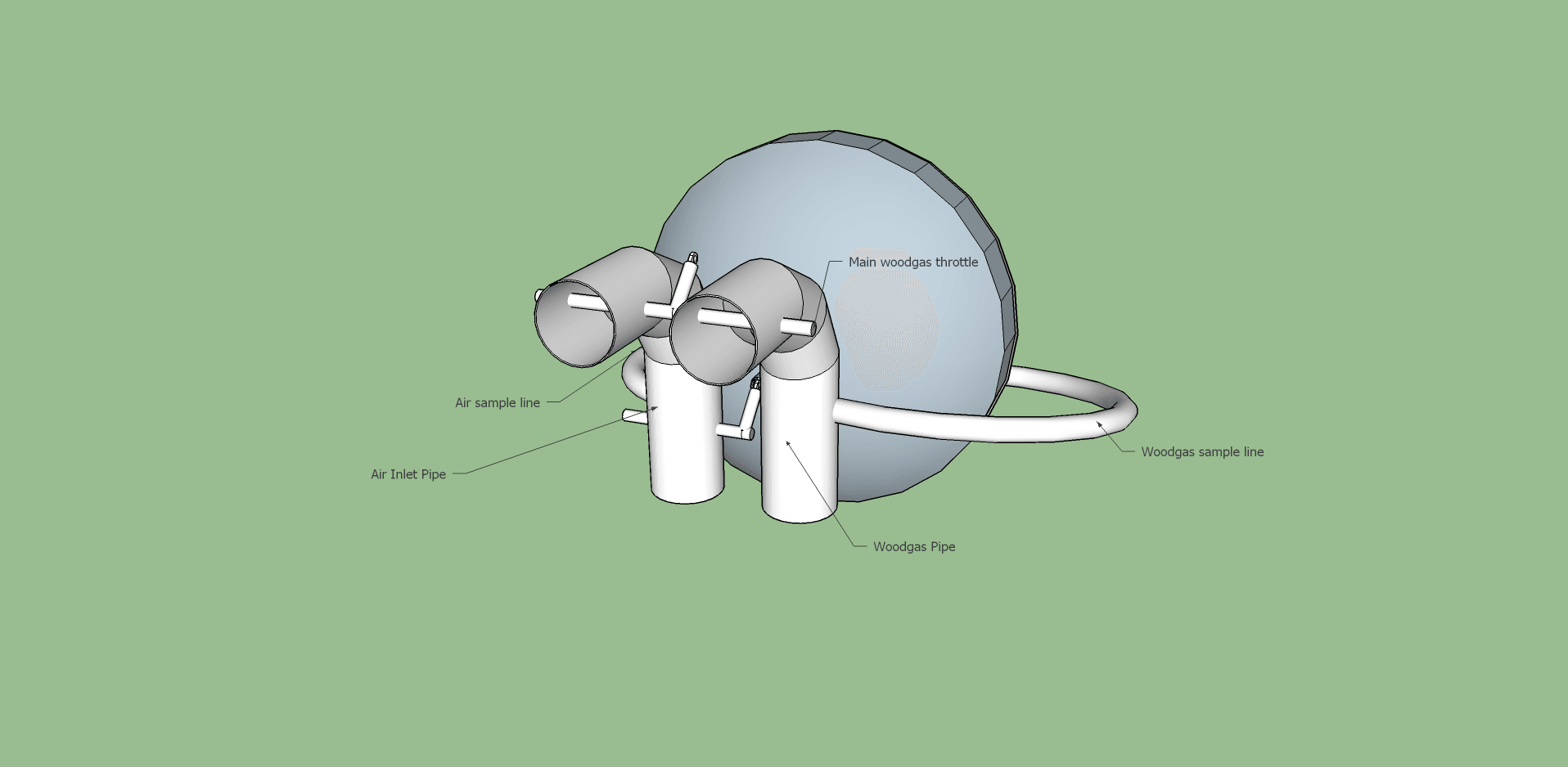
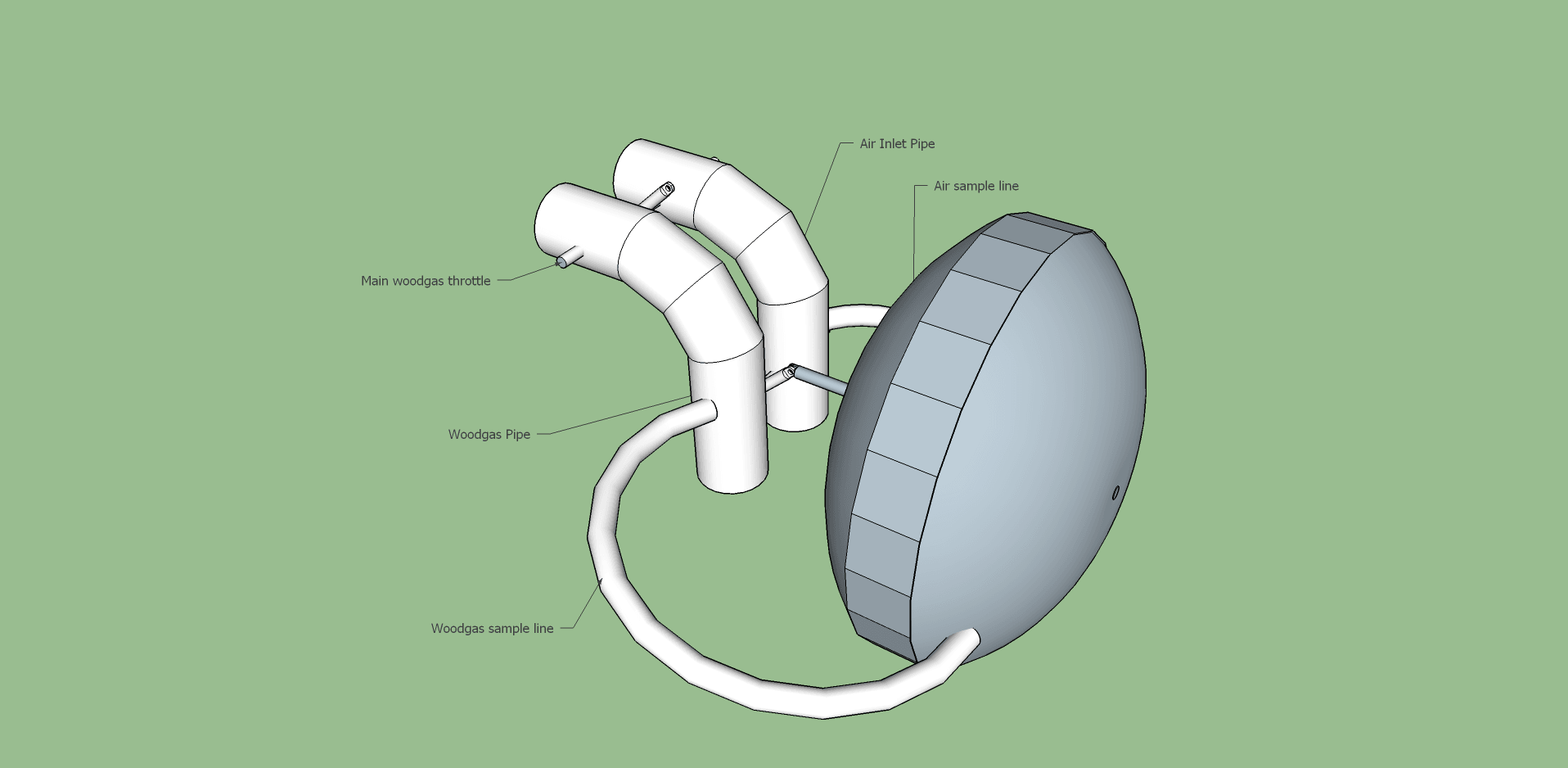
5 Likes
That’s what I’ve said the whole time, it has to run on about 1/2" WC differential. That’s about a pound of force on my 9" unit. The only way to amplify is using a larger diameter diaphragm.
It’s not hard to build a linkage that will operate smoothly on this low pressure. Just keep joints and sliding parts to a minimum. In the drawing above there’s only one joint and the valve itself to contend with.
1 Like
Hey Chris, a brother in law had a 6 inch diameter face vacuum gauge years ago that was meant for some non automotive application. It was 0 to 30 inch. If you had that connected to manifold vacuum. I’ll bet you could really tune your mixer linkages in. Analog is so much easier track trends.
Most aspects seem to have been touched upon; still there seems to be a vagueness about the difference between balancing arriving air/gas pressures on one hand AND AFTERWARDS doing the dispensing of the gases.
In a traditional T–type mixer, the handregulated secondary airflap has
2 functions combined:
Reducing the intake air pressure to the same as the arriving gasline pressure.
And
Dispensing the same airflow as the arriving gasflow.
The obvious can be said as:
Create THE SAME FLOW RESISTANCE for air,
as the arriving gas has to OVERCOME.
But,
With the membrane you can ONLY provide EQUAL PRESSURES
in the air– and gasline
BEFORE ANY DISPENSING and subsequent MIXING.
The dispensing happens with ganged TWIN flaps in TWIN throats…
Max, the repeating machine…
3 Likes
would somebody just figure out a way to turn it into a liquid, easily so we can use injection and be on our way!
3 Likes
Max,
Thanks for helping us get our thinking uncluttered. I use a little bypass tube around my mixing valve to lesson problems from stop and go, but I’m now looking for parts to build an automatic pressure equalizer. I’m thinking mylar for the diaphram and two shallow 3" deep cooking pans with wide rims for the chambers. Look for Stainless Steel Heavy Duty 16" Lasagna / Roasting Pan with Rack on Amazon. I use something similar for my safety filter. Gasket and seal with small clamps around the rim–no drilling or welding.
Bruce
1 Like