In Africa you can always remind the keen listners, that this system, developed in Sweden in the -20 ies, has been used in France by the great GAZOGENE company!
Handwash, or truck rim sized membrane chambers were regulating the arriving air pressure to the gas pressure before dispensing and mixing them for BIG Mercedes motors, producing electricity for sale…
Hello MaxG, thank you for re-posting the above from pdf to plain text.
I like your new avatar picture.
Makes you, real, and friendly, and human. (not a parrot answering machine at all!)
Regards
Steve Unruh
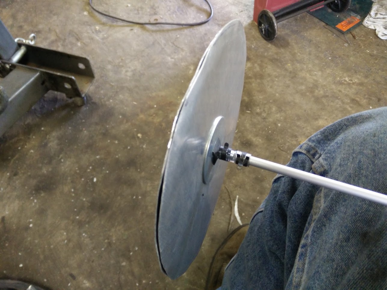
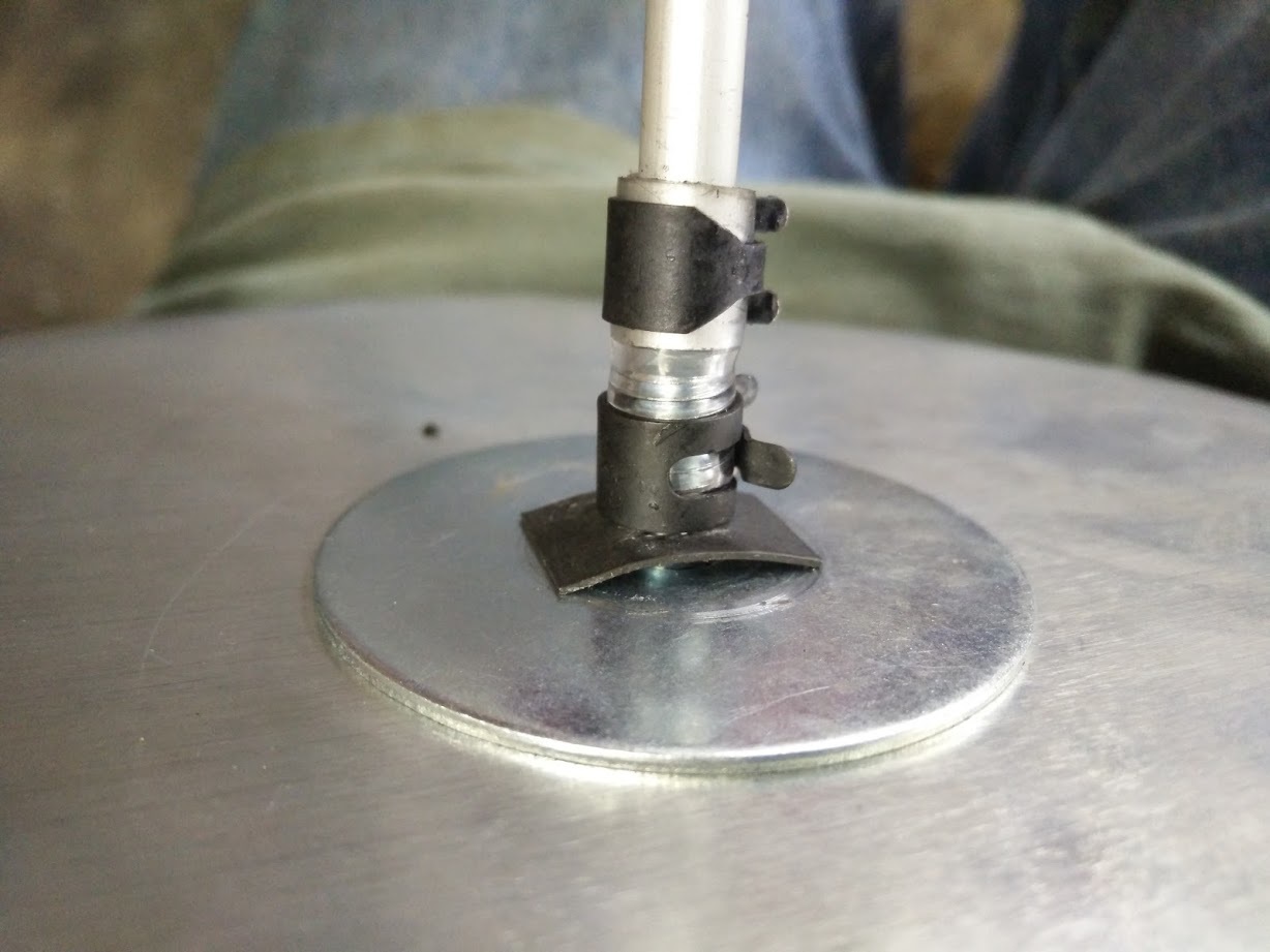
The two circles are held together with a 1/4" bolt, fender washers are used to hold the aluminum plates. Diaphragm itself is not shown, would go between the plates. I fastened the bolt to the rod by a rubber hose and two clamps. I couldn’t find a small enough Fernco coupling so I made my own.
The small black square is a “speed nut”, made from stamped sheet steel. This eliminated the thickness of a standard nut, which saves space in my setup. Every millimeter of length on that tube means less piston travel in the forward direction, since it cannot pass through the casing. The mechanism as it stands will have about 1.5" of travel.
Threading tools would have saved length and sturdiness, as well as “deassembliness”!
One stainless nut on each side of the fender washers…
Some low degree Loctight…
Hopefully the aluminium sheet peripheries are rounded and VERY smooth, in order to not “abrade” trough the delicate plastic.
The same goes for the flange inner edges…
A tight cramping periphery (between the sheets) will avoid the “plastic” to “travel” in and out in the radius’ direction. Maybe some silicone would make a “grip”, if the aluminium sheets are too timid.
Good ideas Max. I will definitely use some Loctite, and silicone, to make sure nothing moves. I also plan to set up the aluminum discs in my drillpress so I can sand the edges smooth and round .
Guessing you mean a shunt tube parallel to your air flap on a T-mixer?
Please! Drawings, sketches, pictures all make it easier to avoid failing fantasies about what the other is meaning and presenting!
16" pots! That’s for big powerplants like GAZOGENE! Are you going “Big Time”?
In the meantime, a few thoughts about the twin flaps, and were they are best useful, and where they are least useful; it is ALL about WHERE the DOMINANT resistant is, and is it under our control — or not.
Continuing, when finding the keyboard control for fattening fonts, instead of capital letters…
Max, I am wondering why we are re inventing this system. Do you already have it on your system. Hasn’t Dutch John given us details on his system?
Chris it seems to me like you are trying to get too much motion out of this system. Watching Dutch John’s the rods appear to move only 1/4 inch or so.TomC
It must have full control over the intended throw of the valve. Otherwise it can’t effectively set the air flap position; you can’t predict where it will need to be.
DJ’s mixer moved a 1/4 inch on a sudden throttle increase, yes. But the full range of adjustment is larger than that.
Yup, gasification will never be linear, we are getting close though. On my set up my in coming air vs gas ports are 1:1 and Ive watched it use just about the full range of the valve. Most of the time its about in the center, but especially when quick throttle changes occur it has to move the full range and do this fast.
Like a mantra: The membrane mechanism is just setting the separately flowing intake airpressure
at every moment to the same level as the inflowing gaspressure, as long as there are two separate gas and air flows to be dispenced (metered) later
In the next stage!
Only in the next stage of operation the ganged twinflaps will do the (still) separate meterings of gas (in one) and air (in the other) flapthroat!
Only after this dispensing (metering) can we talk of mixing gas and air!
Best way of mixing the metered gas and air, is to lead them (still) separately, symmetrically into a swirl chamber and then into the intake manifold.
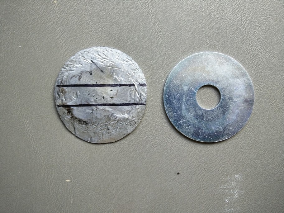
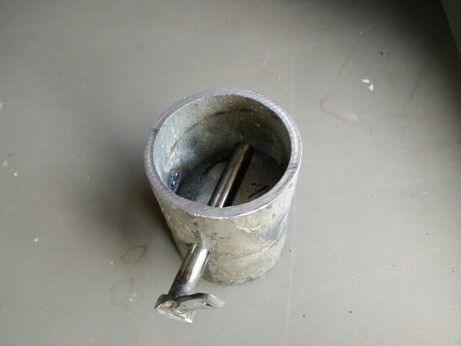
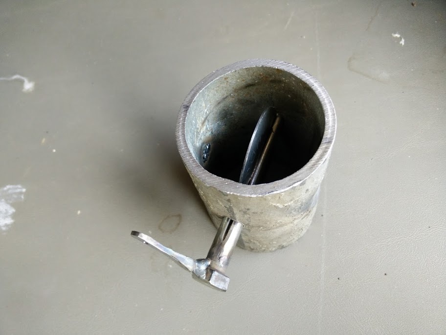
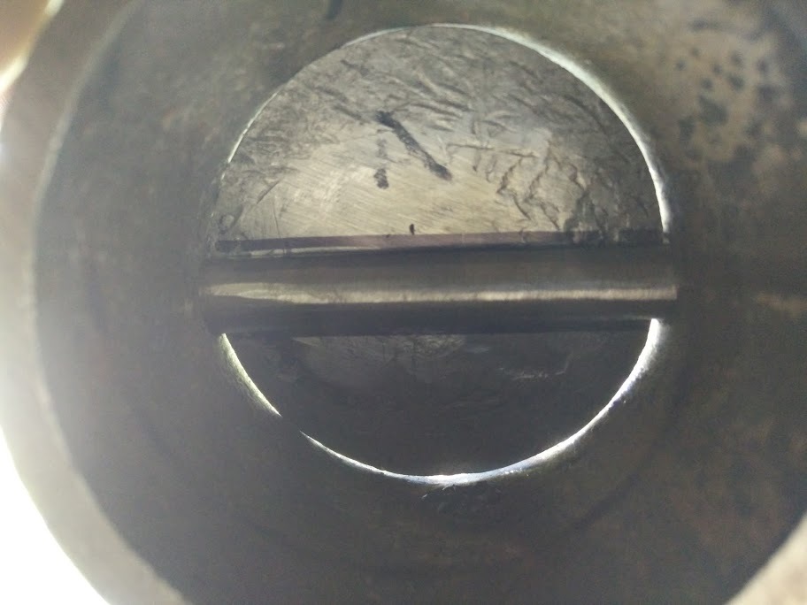
Air flap is nearly done. It needs to be a relatively tight fit; I used a technique I’ve seen Wayne demonstrate, also suggested by Arvid O.
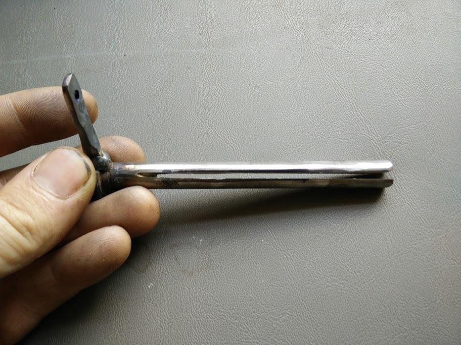
Starting with a 1/2" fender washer which is 2" overall diameter, I welded up the center hole. Then I hammered out the metal on the north and south sides, leaving east and west alone. This quickly adds 1/8" or so of extra length and makes it oval shaped. After filing it down to fit, here’s the end result, compared to the original:
This is pessimistic and skeptical Tom. Back a ways didn’t you say this had to be perfectly balanced and you are going to use bearings to make sure it is free to move with the slightest pressure/vacuum differential? That handle or arm is going to through this whole thing out of balance. Instead of the arm I would recommend a circular disk with a very light cable that would wrap on the disk as the butterfly rotates off center. Sorry for intruding, I’ll go back to watching my paint dry.TomC