I got my hands on someone’s used FEMA gasifier which I’m looking to modify to be more like Imbert according to the following youtube video. If you read the comments, he says that he no longer gets any tar!
So what I’m trying to figure out is how long to make the air pipes for my gasifier.
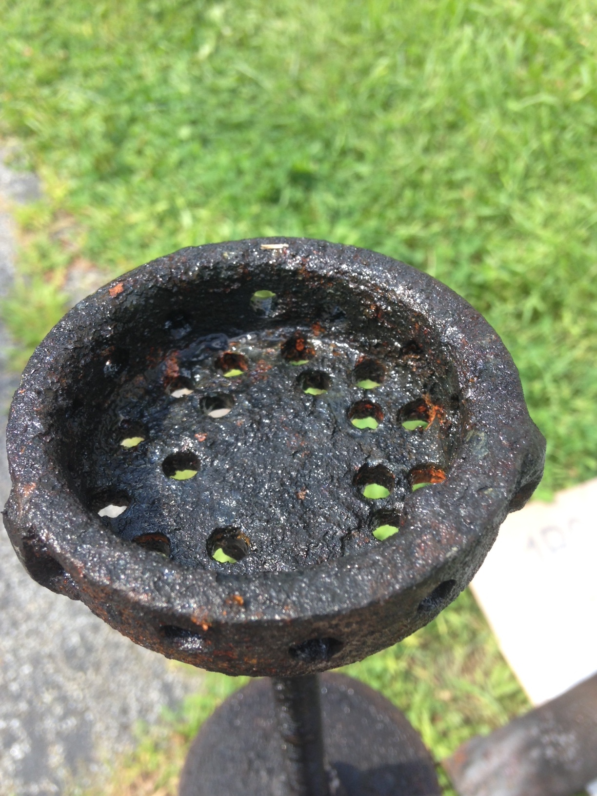
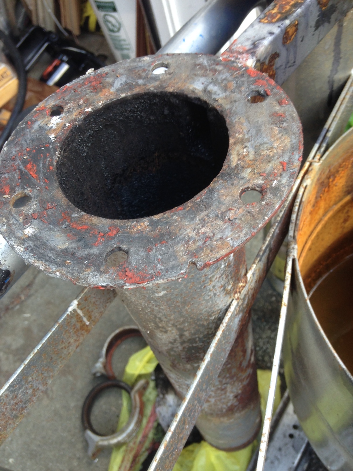
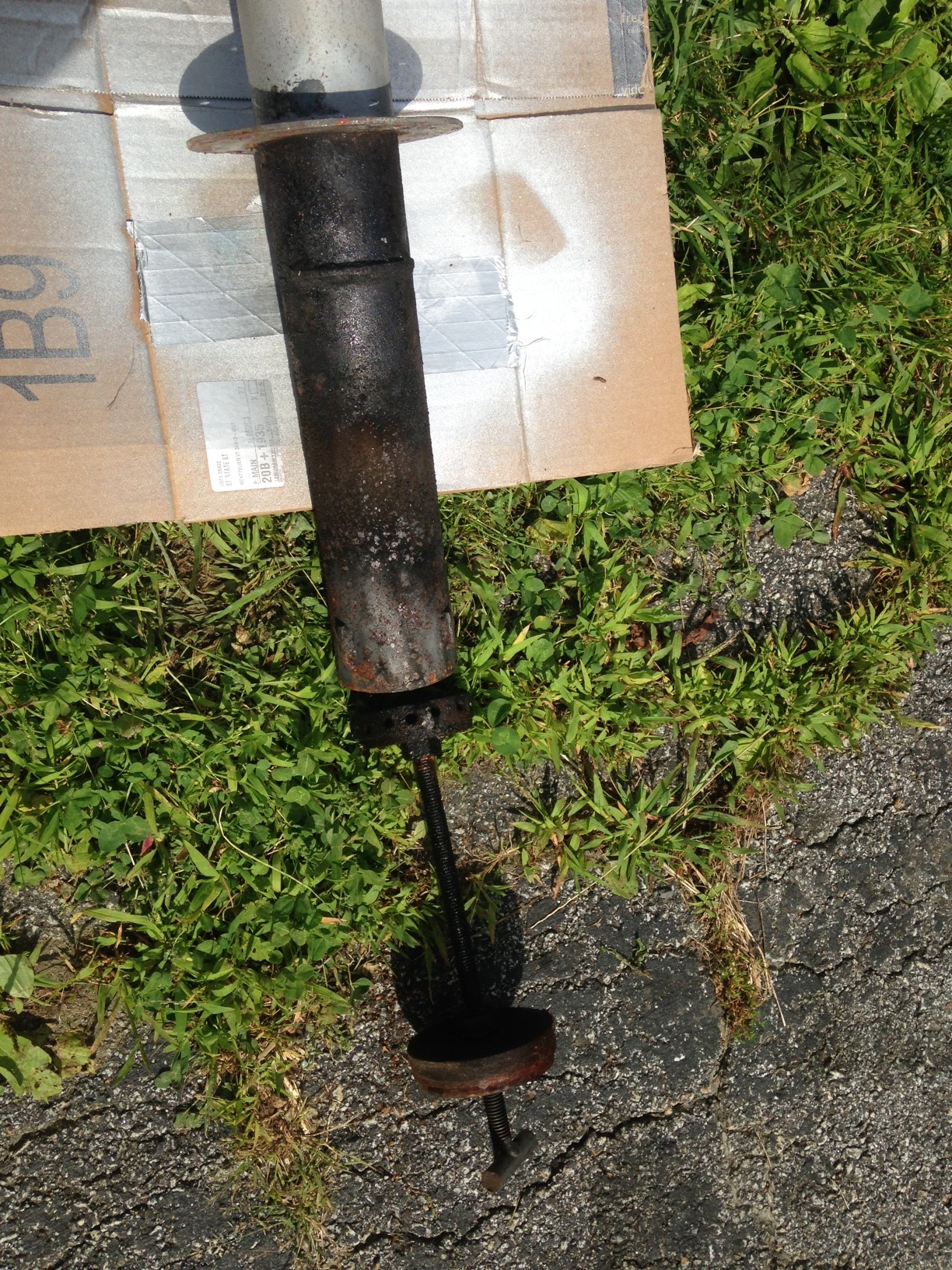
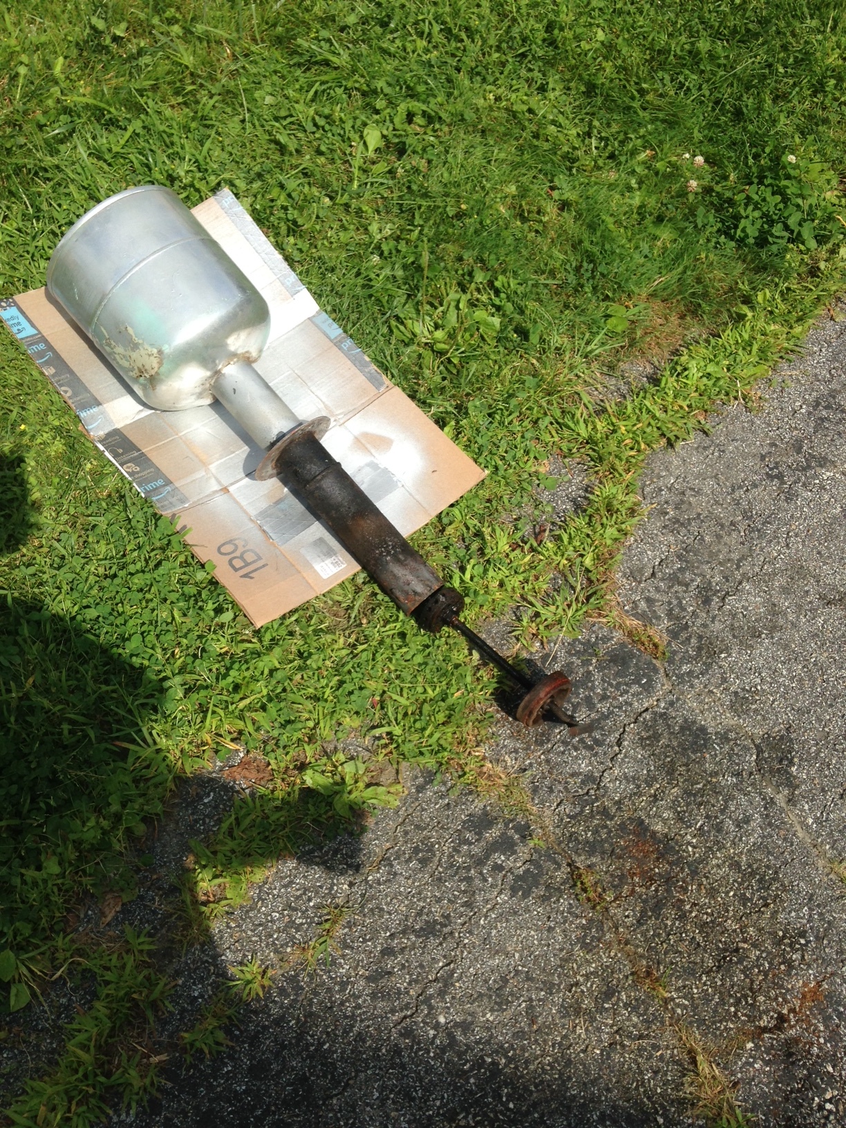
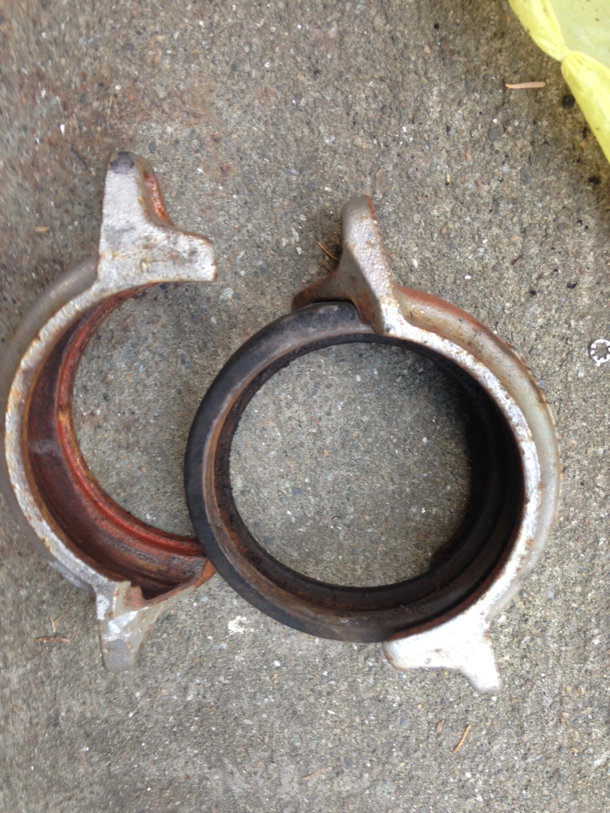
Here are the photos of my gasifier - i took it apart to clean it up and give it a fresh high temp paint coat.
Is that handle to adjust the grate?
I’m guessing the assembly is to be mounted in some king of metal container?
I would weld a sleeve around the fire tube after I drilled holes in the fire tube. You can use the holes in the collar as air inlets. If you go this route, you have to make a new collar wider than the collar you have to mount it on the container.
That looks small for a car motor, maybe it was burning pellet or larger wood chips sorted ,like most fema generator units. The problem with fema is open top air control gets out of ballance at diferent stages in between refills, i Think anyway. That looks like it wood be a way too make some much better consistant wood gas, long as wood it dry enough & if the top is closed tite.
I had trouble relating the guy’s burn tube/nozzle assy to the whole FEMA gasifer that he showed toward the end of the video. I thought that the original FEMA had a much bigger fuel area than that skinny tube that he showed with his new nozzle assy…
From my experience with the JXQ-10 gasifier, which is also an open top machine, the volume of that tube with the nozzles is too small to do any amount of real work. He’d be refilling about every 5 minutes if he were running that engine. But I like the general idea of the nozzles. HOWEVER---- in practice, I think the pipes going down to the nozzles would cause a lot of bridging with wood chips…
The handle is not to adjust but to shake/rotate. Rotating that bottom handle just rotates the grate.
Whole assembly is mounted in a cylinder slightly wider than the fire tube. Unfortunately the clearance between the fire tube and the outer tube is not enough for bringing air in outside the fire tube… 1/4" clearance at most. Unless i do 6-8 small tubes…
A FEMA style gasifier is the first one l have run. And tarred up my first engine with it. Plus it was a 2 stroke
But some time has past since then and l think you can make a decent gasifier out of it in a couple of hours.
You didnt give us any dimensions but lets take a wag at this.
drill 5 1/2" holes 4" from the top flange.
-weld or scemrew in drillded ss bots. Hole in the bolts about 1/4". Protrudeing anout 1/4" in the firetube.
make a mantel around the firetube, airtight, for air manifold/preheat/firetube cooling.
add in a restriction about the same depth as the firetube diameter. Restriction about 2" wide.
Set the grate about one firetube radius lower.
Yep. Yep.
90% Ben Peterson’s 2007/08 era EPS system. Ran open topped with the commercial fuel woodpellets providing the upper air-in restriction. Calculate running time just right to leave NO unheated seared/blacken/sealed pellets on shutting down.
Or have to dig out decomposed pellet sawdust on the next firing up.
S.U.
Can you kindly explain this: “make a mantel around the firetube, airtight, for air manifold/preheat/firetube cooling.” do you have a picture or drawing of this possibly?
When designing for low HP (say <20hp) is the only fuel possible wood chips/pellets/etc?
Based on the imbert empirical design rules the restriction would be what, 40-60mm, I assume
large chunks (~2") would clog a small system like this? Forgive me if my terminology is less than
proper - I am still very new to this
Fuel sizing is where you have an opportunity to learn and try different things. You can try pellets, chips, 1" chunks and then try going bigger and see what happens. Try mixing two together. Chips and chunks, pellets and chunks, pellets and chips. Find out what works best. Softwood will be different than hardwoods. Just make sure it’s burning hot enough before you hook up to an engine.
I know that this idea is old, but----
Why not bubble your gas through water to get any tars out on its way to the engine? You could use this process to evaluate design changes until you get the data that you need.
Make a run.
Empty the water chamber
Evaporate the water
Weigh and evaluate what’s left.
(you may have to cool the water chamber if it is small or if you are making long runs)
This way you don’t clog up your engine on your way to the “perfect” design. Then, once you have it right, eliminate the water filter.
Following construction principals in some of the library books and using one or two sheets of paper makes more interesting results than random guessworking…
Everything starts with the motor’s displacement and RPM, “rounded” by the degree of load.
All critical flow areas are in direct proportion to the calculated gas demand.
That applies to the process volumes too.
The practical formulas are plain multiplications and divisions, and a few calculations made by internet formulas only needing an input of diameters and height.
Then the fuel size will also appear as how many bits needs to fill the upper hearth = oxidation zone.
The only formula on the internet needed is a “conical frustum” calculator, which will sort out the measures for a needed hearth volume.