My first small engine run

The second fix is the pressure cap leak. At first I thought the double gasket failed but found the welds holding the threaded studs were spotty and leaked out through the space around the studs.Note tar on base of studs.The double gasket worked.
I rewelded the studs and will replace the gaskets as well

UPDATE: 1/29/13 I scrapped this design as neat but over built. I see so many simple pan like covers that I’m going there.


Continuing on with the tear down, I disassemble the unit for inspection.
Pic 1- Components
Pic 2- Char in base with briquets that fell by grill sidewall space on first load up. New grill will have only a 1/2" space to sidewalls.
Pic 3- Air inlet 90’s removed in prep for single port air inlet. Port location to be determined after cyclone heat reclaimer is tacked in place. The 8" cyclone will fit inside the 10" tube heat reclaimer.The round gas outlet pipe was removed. Square flange bolted connections will be used instead.
Pic 4- T minus one to separation
Pic 5- I used a flat bar to gently pop the flanges apart so I could lift the unit off without disturbing the rope gasket. I was concerned about the integrity of the butt joint that I sort of layered together. It looks OK, no evidence of leaking.
Pic 6- A closer view of the gasket joint.


Hi Pepe,

Amen on the briquettes ! I do not even use briquettes for meat when I cook because they have a bunch of filler ingredients, and make much more ash than real wood charcoal like Royal Oak or even Cowboy Lump that we have in stores here in NY. For startups, You would have a hot fire in no time using natural lump charcoal and throw in a few handfulls of stove chow (wood pellets) ever now and then because these little logs catch on fire easy and they turn into usable charcoal much quicker than natural wood. The little stuff helps dry out and burn the big stuff.

On your post from 18:19 today

I have questions about the [reduction bel | 4" restriction | choke collar, etc…] that is shown on photos 3-10. Is the purpose of this part to make all of the hot gas pass through the hot char and flow only through the 4" hole then to the grate ? There seems to be a pretty large gap directly under the nozzles along the burn chamber walls where this restriction part does not appear to touch the walls at the top. Does this part have a flange on the bottom or something that makes a seal so that the gasses flow properly through the 4" hole ? Looks like that would be a difficult design challenge to overcome if using nozzles that are not removable so they always stick into the burn chamber…

I would guess the grate would probably be OK unless the holes are too big (?)… the real problems seem to be above the grate - briquette fuel and any leaks around the 4" restriction hole.

GG Edit - I paged up a ways to 07/21/2012 - 18:14 and see that the restriction cone bolts in from the bottom and there is a flange, so everything should be going through the 4"hole if you build as good as you draw !

BTW… I have my eye on my JD524 snow blower for my first run - thats how we roll in NY, right ! Save all that pea sized charcoal for me because I would use it in my ammo can filter or even burn it in my lil gasser… I’ll even stop by to pick it up !

Hi Gary,
I’m in the Mooers, NY area a couple of miles from the Canadian border in the real upstate NY.LOL. How far upstate are you? When politicians refer to upstate NY, they usually mean 10 miles north of Albany. Lol.
I made some progress on my improvements list. I’ll end up taking all the sections apart(only have the burner insert to remove tomorrow) to inspect gaskets, etc and make the retrofits easier. I think. I need to hook up some rope and pulleys to pull it out and not to damage the gasket putting it back together.
I welded in the single port air inlet jacket, but will not cut the inlet until I have the cyclone(8" D) and cyclone preheat shroud(10" D) figured out and tacked in place. I then cut off the cyclone cone(13" L) and welded a 13" straight section to it. I’ll increase the cyclone outlet to 2’ D and add a 2" X 4" cyclone inlet that will bolt to the gasifier outlet.I hope.
Pic 1 Hourglass hearth with flange
Pic 2 Hearth bolted to bottom of fire tube, The sand on the floor came from around the hearth, all the junk you saw. Next time I will pack it more fully using damp sand. The fine sand really settled a lot during operation thus the charcoal stuff seen in the old pic.
Pic 3 Serendipity
Pic 4 I trimmed the excess and welded it in. I can’t believe I was so lucky.
Pic 5 The fire tube flange was part of the circle left from cutting the flange below it. Not planned just another good fortune!
Pic 6 My new 26" cyclone unit ready to mount in/with the preheat shroud. This should be a challenge. Can’t wait to tackle it!
Have to take a break now to finish picking blueberries before my honey gets home.
Pepe


I pulled out the burner insert and the rope type gasket looks really good, but I will replace anyway. Then I can set up for the cyclone and cyclone heat recovery adaption.


Hello gasifier enthusiasts,
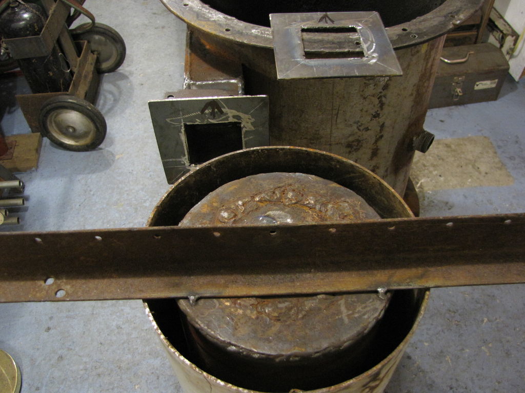
I got a start on my 26" cyclone project today. I extended the square gas outlet 2" and cut out a couple of square flanges for the “to be bolted” interface. I hung the cyclone in the preheat recovery shroud to get a sense of its tangential line up with the gas outlet. The tangential inlet to the cyclone will pass through the preheat shroud and will be welded to it in the final assembly, which will then bolted to the gas outlet flange.
The preheated air from the 4’ stove pipe around the S cooler sections(see 7/21/12) will be drawn in at the bottom of the cyclone shroud and end up entering the single port air inlet(Pic 4 above) as well preheated air.


Hi Everyone,
First pic- I thought I would add 2 fins to each air inlet tube for preheating. They would both be welded to the inlet pipe and the burner wall. Is this robbing Peter to pay Paul or a good idea?
Second picture- Back to a full size dwg for an accurate placement view before I start the build. Most definitely not a waste of time. The inlet and outlets need to line up well for an easy airtight interface. The single inlet air intake will be last in the line up here. It will be sited between two of the air inlet openings with a vee diverter in the port opening.
I’m a happy man, I took my wife to the airport today. lol. What I’m happy about is her sharp eye out for me. She spotted this trailer in a yard about 15 miles into our trip. I stopped back on my way home. looked it over and bought it for $100 firm! It was on a small camper trailer frame. Drove it 3 miles at 35mph, stopped and felt the axle, bearings cool. A little faster and another stop, bearings still cool. Drove hws the rest of the way and it tracked very well. Great! It even came with a propane tank holder and a small wench, er winch. Sand blast, prime and paint, inspect, clean and/or replace bearings and grease seals, add lights and a new wiring harness, geez it’s spring again. lol! Looks like the old wood splitter was spared the torch! Thanks, babe.
Pepe

Edit. I didn’t do the fin thing on the air inlet pipes. I also didn’t do the air diverter, this one I just forgot! Trailer still waiting for some tlc. lol.


Hello Fellow gassers,
I finally got some time to work on coupling my cyclone to the gas outlet via square flanges.
First pic- shows the flanges match drilled and the gas outlet flange welded to the gas outlet. I jockeyed around the cyclone to get the line up of the cyclone inlet to its square flange. When the line up is good, tack weld the square flange to the cyclone gas inlet. Now you can remove it for easier welding. Note I changed the cyclone inlet cross section to 2".
Second pic-The foot print develops with some solid connections.
Lasr pic- Once the flange is welded, I will put the cyclone in the white tube, bolt the flanges mark and cut a slot for the inlet to rest in the shroud. The circular plate on the bottom of the cyclone will seal the bottom of the white tube. The white tube will get out fitted with an air inlet on the bottom (from the cooler shroud) and an air outlet at the top. coupled to the single port air inlet.
Ran out of argon/C02, manana.


Hi All,
I beat the sun to the shop this AM and was able to weld the flange to the cyclone inlet, mark and cut the slot in the shroud for the cyclone gas inlet and check it for alignment. It looks good. I’ll take the shroud off and weld in the air inlet and outlet before I close it all up into a single unit. I also cut the inlet and outlet curves on the 2" X 3" tube and test fitted them. They look good, now I can cut them ot length and install them. I have to remove the cyclone once more so I can make an inside weld on one side of the inlet and outlet. It may not look like it but in the third pic there is an even 1" space around the cyclone. The next to the last pic shows the plate on the cyclone sealing the shroud bottom and the air inlet tube for the cyclone shroud air preheater. Char collection will screw into the bottom of cyclone.
The last pic shows a straight shot from the gas outlet into the cyclone.
pepe


Lookin’ good Pepe.
You can pull heat out of the cylone as long as it stays above condensate dew point.
You could always use system surplus heat to open air dry fuel wood. being able to use all seasonal wet picked up wood is the real goal to a home stationary system.

More eveidence of my mantra of “Run With AN Engine Always”.
My new engine system keeps blowing my hat off from the exhaust pipe. One of my previous engines a diesel Listeriod would do the same. I’ve been ring seating in this newest Kohler V-Twin loading the genrator down with my two shop blowers. These things proven they can suck “Pick up a bowling ball”, pressurized a gasifier to flare and the impeller size and speeds are exactky the same size as we built the Victory Shop “HummingBird” suction blowers around.
The exhuast from this Kohler engine at it’s 2600 RPM loaded engine idle is out blowing my shop vacs.
Over on the YahooWoodgas groups Stephen Abadess has put up a plumbing fitting ejctor flare nozzle he sucks his gasifiers with that he is BLOWING with a shop vac. I am sure now the exhaust off of many IC engines at power and speed could power ine of these ejectors too.
Eliminate the blower assembly and motor comletly and simplify.
( There you go MikeL - a plug for the other groups)

Regards
Steve Unruh


1 Like

Hi Steve, Your new unit looks like it could power a race car, but the Lister is a thing of Beauty for sure.
Thanks for the condensate dew point info. Perhaps I should put in a tee in the line so I could temper/close off the preheat air at some point.
Stephen Abadess- Now I remember where I saw that name.
Later, Pepe

Hello fellow gassers,
I made a little progress on my cyclone heat recovery/preheated air modification. Thought I’d share a few pics, the last of which is a candidate for fan housing find of the week. The ID is 8 3/4" and it is 4 1/4" deep. The feet can be cut off and moved around the corner to allow for a flange to mount the fan motor to. Yeah, it weighs 8 to 10 lbs. The cyclone is now (gulp) buried in the shroud. The shroud will get 2 drop down lockable leveling legs with half moon feet to help stabilize the unit. The 2" threaded gas outlet tube will get a union for cooler location options. Ideally the top of the cyclone shroud and the top of the SPAI housing should be even( didn’t have a long enough piece of tube left)… Next time. I’m onto forming puffer top and other RTV gaskets so I can put it back together. Getting closer to a refire, with real charcoal, of course.
The road to here ain’t been straight, but when this thing doesn’t react as it should, I’ve now got a pretty good idea of what to look for and where. The tear downs, along with knowledge of the steps of the process are a great learning tool and part of that 75% builder/operator learning curve.
Regards, Pepe


looks cool… keep up the good work

Hi All,
I finally got set up outside and successfully ran my roto tiller on wood gas. I have a long version and a 30 sec version for dial up folks.

roto tiller on wood gas 1 2m 20s

roto tiller on wood gas 1 30 sec

Hi All,
I’m dismantling my outside setup for some tweaks. I’ve also made a mold for making high temp silicone gaskets. You can adjust width and thickness easily, but I think a square cross section will work best for circular gaskets. I’ll wait a couple days and test for curing. I’ll post the results.
For testing I plowed 2 3/8" x 3/8" grooves in a 5’ 1" x 4". I figured 5’ would do a 19" diam. Sand the grooves well and varnish 2 coats. Sand and clean between coats. Very lightly paint veg oil on all sides of groove Fill groove using caulking gun. Fill entire length with silicone just barely proud of the face of the board. Strike it off in one motion the entire length. Let the excess come all the way with your sweep. Use a teflon pan scraper, it’s no stick and leaves a smooth finish. Don’t dally, the surface skins over quickly and if you go back to smooth it over, you’ll drag chunks along and make a mess. One 14 oz tube made 11’ with about 2 ’ of waste from strike off. Don’t use it, it has veg oil contaminate and may just pull apart after curing. Don’t overfill the grooves or you’ll lose a lot of silicone. Cut to length and glue ends together with more silicone and set aside to cure.
Can’t wait to pull these out of the mold.
On another front, I have a silicone gasket failure due to too high a temp gas. This failed where my gas outlet joins the new cyclone arrangement, No, it’s not a smoked snake, its silicone. My mistake, should have been rope type.


I thought I’d update my gasifier dwg to reflect design changes. Notably, they are the 2" x 3" single port air inlet manifold and the 2 1/2" x 3" gas outlet. Both of these are flanged to accept the new longer cyclone enclosed in a shroud to preheat the inlet air.
Learned from the snow blower run…don’t run syn gas through the carb, it will deposit some tar on everything in the throat. Yeah, it’s soaking now, lol. Remove the carb and make an adapter for syn gas entry.

I found a fantastic small engine repair Channel. Go to youtube and type in donyboy73 Channel
The best detailed how to videos on small engine repair I’ve seen yet.
Enjoy, Pepe

Hey Pepe, check out this tape. We have been using for some time now and it is working great. We use this on just about every thing except for the lids we use rope on them.

It is very cheap too. For ten bucks it will go ten times as far as sylicone for the same price and you can take stuff apart and put it back together with out the need of re applying it.

1 Like

hey matt, i see there is alot of seals listed which ones do you use.
Jim

Hi Matt, Thanks for the tip and I ditto Jim’s query, can you be a little more specific?
Thanks, Pepe

Sorry about that, the link was supposed to bring you to ones I use. Strange how that works. But any ways the “slotted fiberglass seals” are the ones we use. We get the adhesive backed loosely woven. If needed you can get the spay on copper silicone and apply this to the the opposing flange. This will ensure a good seal or you can apply the tape to both flanges.

8813K31

1 Like