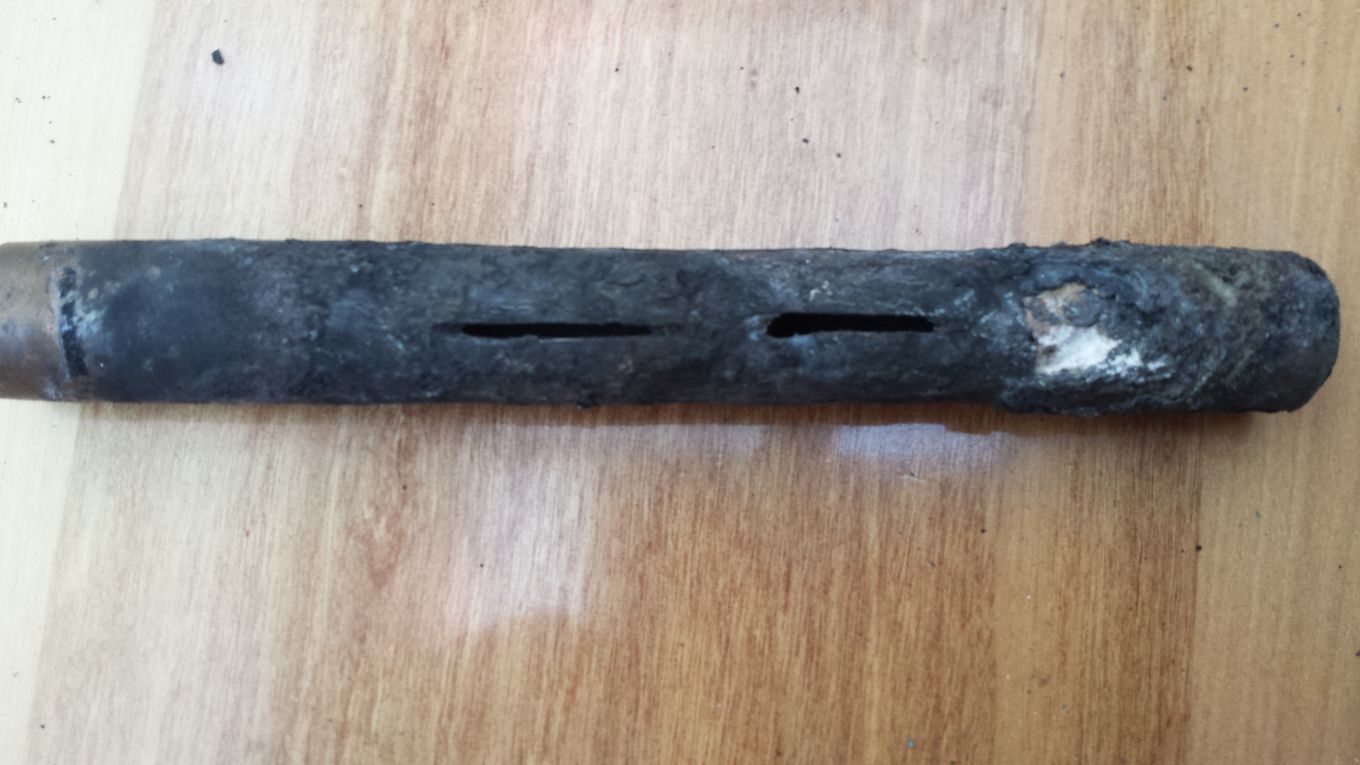
The reason for slots rather than holes were simple , my drill bit was taking forever to get started on the stainless pipe and my battery was nearly flat in the drill
and grinding is so easy and fast !
Ok I have thought about this all day and I am going to try and get to the workshop one day soon and build another gasifier into another large propane tank , what I have noticed with using a vertical pipe with slots/holes is that i think i can modify this design to accept all manners of duel fuels .
If instead of a small 1 inch pipe like i normally always use i shall use a 3 or 4 inch pipe , again seal the far end and use only 2 small slots in the top , and that will allow me to run water into the bottom of the pipe and allow it to run out into a sump on the floor and pump it back up so its circulating keeping the tube cool but also allowing some of the water to turn to steam , or i could auger into the tube all the charcoal fines or wood pellets into the tube and allow it to vaporise in the hot pipe and up through the slots .
What you think worth a try isn’t it .
I am about to go out and fire up the gasifier for the 3rd time of its 4 hour runs , so far 8 hours and still all intact , but i cant see inside the gasifier to see how it looks from the hot zone till i take it out .
Dave
Great looking gasifier and resaults!
l used to do a similar thing on myne. The water was aded at the intake where it flowed to the botom of the nozzle and vaprise.
Not sure for wood but l was thinking to put plastic clipings in it. It wuld boost CO, H2 and methane in the gas.
I heard somewhere of a Pederick-style that used 1/2 inch steel plate with a 1 inch hole. Also the Pederick manual says that water drip must be used or the reactor will be damaged.
The past few times I have started up the charcoal Gasifier I have struggled to get a flare off before starting the engine , sure there was gas there, but remove the torch and it would not stay lit ,also the flare had that orange colour to it when trying to burn , the engine was also a lot harder to start both times , unlike the first 2 runs I did on this stainless steel pipe with the slots in it , my first thoughts were an air leak .
So yesterday I tried blowing through the system and as I always do I spray with soapy water every joint and everywhere else that I have welded up or bolted together , Nothing ,no leaking air bubbles or anything at all .
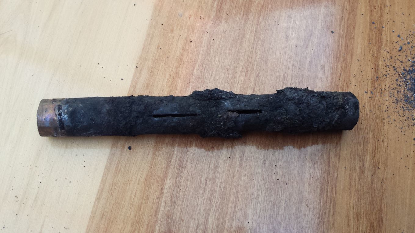
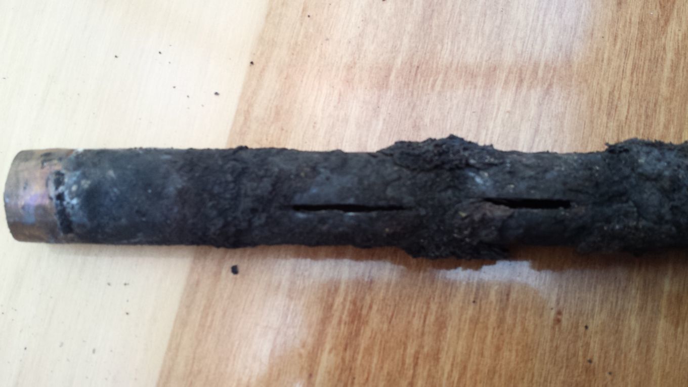
So I decided it could only be the nozzle that may be the cause ,so laying the gasifier down on its side I opened up the large hatch and started removing charcoal out of it , around the nozzle area crumbly slag or clinkers starting started appearing in the charcoal I was removing , but as always just breaks away in my hand , I then get to the stainless steel pipe and remove it and was pleased to see that it looks almost the same as when I installed it last week , be it a little dirtier though .
So I started scraping away the remaining bits of slag /clinkers off the pipe , funny thing though , I could not scrape off the stuff towards the far end on the right of the picture , yet it looked the same as what was around the slots and that just chipped off with a screw diver blade , so a larger blade was used and I started chipping away at it and noticed it was starting to come out white underneath , meaning that the far end that is plugged up with refractory cement and well away from the slots must have ,melted through the stainless and down to the ceramic , how strange !
Anyway that will have to be investigated a little more I think , and I am positive that isn’t the cause of why no flare off or easy engine start , I think the heat transfer from this stainless steel pipe onto the fitting on the side of the tank is so great that the wall of the gasifier got extremely hot in only 5 mins of starting the fan and lighting it and that maybe the expansion of my hatch when hot is allowing air in , because all the charcoal around the hatch has a white dust on it and I am sure I read somewhere that is a sign of air leaking .
By the way I normaly always use a ceramic holder of some sorts to hold my nozzles and that is what insulate the side of the tank from the extreme heat of the nozzle so maybe I shall cast a stainless steel pipe into refractory as I do with the tig nozzles and give it another try .
Dave
I fired new vertical cast iron nozzle gasifire today running the 2.5 hp98 cc Kawasaki 4 stroke spinning an alternator. Engine ran very well but under powered. It worked ok because the pto is on the camshaft rather than the crank giving it a 2 to one reduction. I had to run it at full throttle. My first thoughts are that vertical rather than horizontal nozzles are way less efficient. It seems like this little engine burned about twice the fuel in an hour as I remember using with my 11 hp Briggs and Stratton Mower two years ago. It also seemed to take twice as long to light. Not sure about these results yet more testing to do, to many variables… I am making more charcoal now, will fill 2 gasifires with charcoal from the same batch and run an hour on each measuring start up times and fuel used. I will also try a horizontal nozzle with the end plugged and holes drilled in it. I may change engines and gearing. before any more tests being this little engine is not up to the task at hand. I want to spin the alternator faster with less engine rpm’s. I have a Subaru /Robin engine rated at 3.5 hp at 4000rpm to try. I don.t have a sheave to fit it at this time but will visit the junkyard this week for one. Stay tuned, more to come
Dave - One thing that occurs to me is that is appears the area of those slits is probably quite a bit less than an open pipe or TIG cup. That means that the velocity and the resistance to air flow are probably going to be significantly higher. Maybe that is a factor in the results you are seeing?
Well the hole in the small tig cup I used was about 12mm and the smaller engines I used seemed ok with that , and that’s why I went with small 2x20mm slits rather that straight to larger ones , Kristijan only had 4 x 10 mm on his running a 1000 cc engine , so I can always make them bigger , but means filling in with weld if I have to go downsize , and my engines are only around the 350 cc size
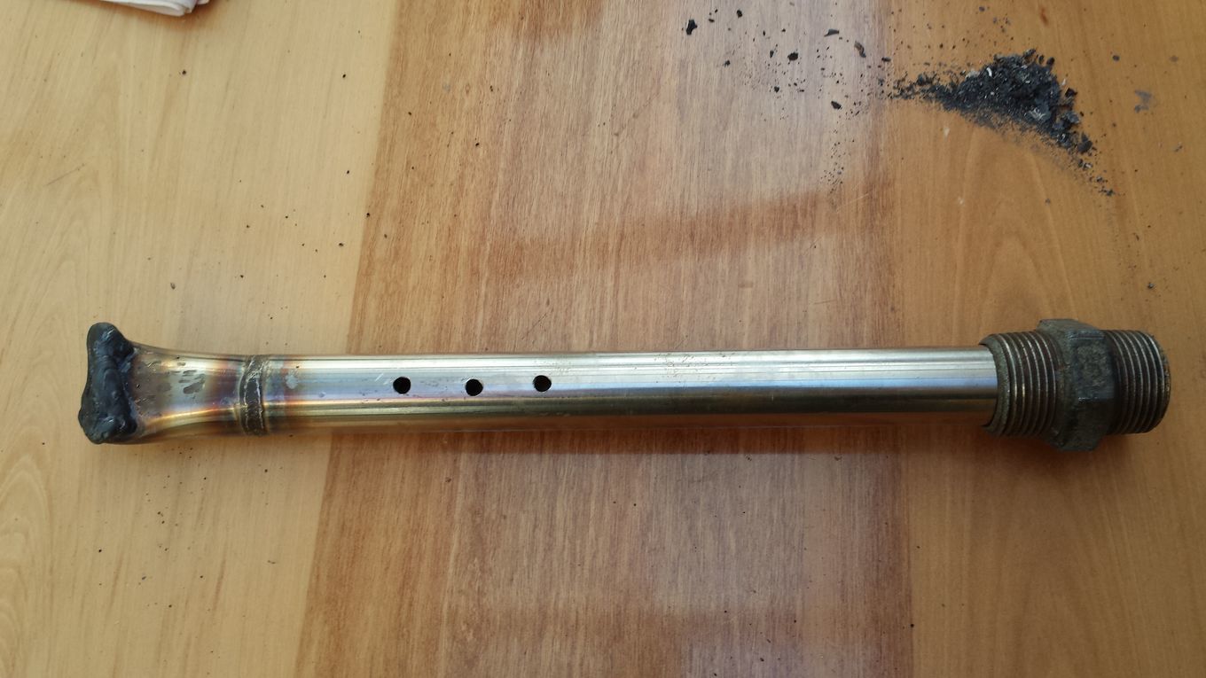
Anyway rather than just put one of my normal nozzles back in that I have ready I have just come back from the shed with a new pipe , this one is a bit longer its 27cm from inside the gasifier tank and I have drilled 3 x 5mm holes that I shall increase once I see how it works , I have moved the holes almost past the centre of the tank and so it wont matter if the back wall of the tank gets hot now as there is no trap door on the backend and so should keep the trap door area cooler , I have also welded up the far end rather than plug it with refractory cement .
I shall have a cuppa , and then go out and fit it in and re seal the trap door and see how it goes .
Dave
Thanks Koen , I was hoping a clever person might do the math’s for me
The latest nozzle is in and engines running pretty good , although I am still not 100% sure there are no air leaks as once again the flare took a very long time about 5 mins to give a flare that would last a few seconds once the torch was taken away the flame its self looked very yellow and that in my eyes is a weak diluted gas , and also again the engine did not start straight away as it normaly does .
I shall be building a new system in the coming weeks so for now I shall carry on playing and trying new things out before this old girl heads for the scrap yard , its lasted over 2 years so I’m happy with that .
Dave
Yesterday , I took out the longer stainless steel pipe with the 3 small 5 mm holes , although it did seem to run the engine ok ,it was under powered and was lacking somewhat and couldn’t get the amperage out of the alternator without the engine stalling , rather than just drill the holes out to a larger size I replaced it will my normal 25mm Tig cup nozzle while I wait see if Koen can give me some idea of the optimum hole size for my smaller engines , rather than just drill the 4 x10 mm holes like Kristijan has for his 1000cc engine though by my workings out maybe I should have just halved the amount and gone with 2x 10 mm holes , I may just do that that today and see how that runs the engine and see if I can get a full load on it .
Its strange to think that I have been running all these small engines and generators for a few years now without thinking about it and getting pretty good runs over that time with only a few minor issues with the odd air leak here and there , and as soon as I try and fine tune it then it goes off balance , oh well its fun learning I guess and better now rather when its really is needed in an emergency .
Dave
Thanks Koen
I had noticed that one of the 5mm holes had blocked up with slag , and wondered if I might leave it blocked up and just try the 2 holes and take them out to 10mm each I guess that would give me about 157 and that’s more than double what I did have .
If that doesn’t seem to work then I shall start over with new pipes and start with 1 hole and keep increasing the size or number of holes till I get a average good run on all engines ranging from the 80cc up too the 500cc inverter engine that I use .
It may turn out that I have to swap tubes every time I change engine sizes as I guess there wont be a one size fits all when it comes to getting the optimum power from each engine .
As I have mentioned before, up till when I started playing with these horizontal nozzles all my engines seemed to run ok on the 25mm tig cup although I do have to adjust on the go to get the max power from engines when I go down to my smaller engines . shame advancing the timing on most of these units is awkward .
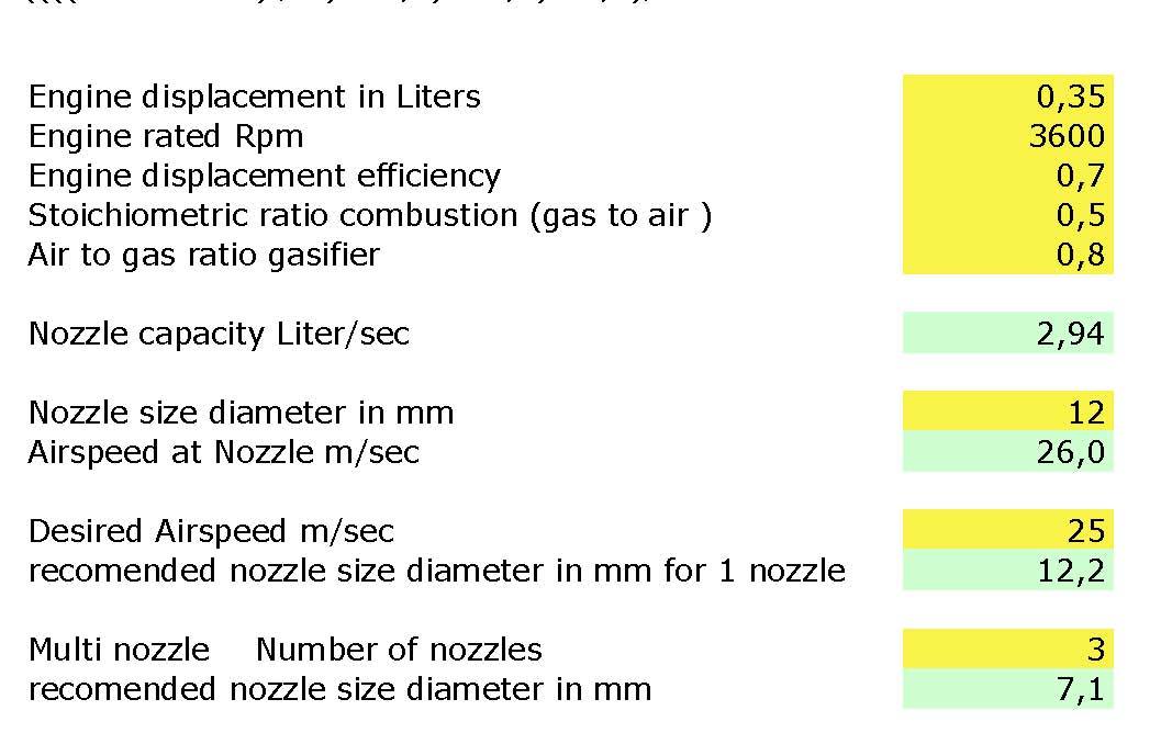
This is the spreadsheet i did build for the nozzle sizes.
If you see what nozzle size is giving you the best results, then ad that number and you’l see the airspeed.
Then ad that number at the desired airspeed and hoppla, you have your sizing.