Don,t you just love those plastic dash for mounting choke cables!
I put a piece of 16 ga steel to cover the blown out holes and provide the support they need
Don,t you just love those plastic dash for mounting choke cables!
I put a piece of 16 ga steel to cover the blown out holes and provide the support they need
That happens to me too! Don’t you just hate when that happens? NOPE!
That is why Dodge is the preferred model to use for Gasification , the plastic in the dash is tougher than Ford or Chevy trucks. Ya Right. Lol
Bob
There plastic comes from a better class of dinosaurs. Lol.
Must be T-Rex plastic! 
Another baby step, really just poking at this project for lack of time to do more. But, progress is progress…
I had a good look at Henry’s wiring. It looks like a mess, but he used a lot of terminal blocks and labeled all his wires… This is by far the best documented custom wiring I’ve ever inherited.
The thing I needed to change here, was the fuel pump wiring. This truck has a TBI, which means the injectors need to be shut off as well as the fuel pump. Henry had the fuel pump on a switch, which was on battery voltage - meaning the relay would stay on all the time if you forgot the switch. The injectors were on a separate switch which is also easy to forget about - if you leave it on unintentionally, it will run “really good” on woodgas. If you leave it off unintentionally, it won’t run on gasoline. For my purposes, it needs to go on and off with the fuel pump. The fuel pump needs to go off with the ignition. Easiest way to do this is by using the fuel pump power to run the relay coil - it already comes on and off when it’s supposed to, and runs in the crank position (unlike accessory power).
Taking a closer look at Henry’s fuel pump switch, it looks like he lifted the ground wire on the rollover switch or something like that… not the power to the fuel pump relay. Because of this, I didn’t have 12v+ fuel pump power anywhere near the relay. Instead of messing with that, I just ran a new pair of wires to the fuel pump relay fuse, located on the passenger side firewall. Bingo! I now have control of 12v+ to the pump, which is also a 12v signal telling me when the fuel pump should be on.
For the twin injectors, Henry had already run them to a double pole switch. All I did was substitute a double pole relay, which is controlled from the same place as the fuel pump switch, the 12v feed to the fuel pump. Now when I switch on the fuel pump the injectors get power, and when I switch it off the relay opens and they are instantly shut off. And with the key off, no relays are left engaged, regardless of fuel switch position.
I’m aware there is a use case for leaving the injectors on and pump off, for “trickling in” some gasoline for a mild hybrid mode. For now it’s not what I want. If I do ever want it, one more relay on a switch will allow me to manually unlink them and power up the injectors without the pump.
Doing a great job Chris, Thanks for the share
Henry does good work, but not to discourage the beginner, it’s really not that complicated. I’m not a neat person, but it works, and I can fix it. ![]()
Another bit of work. I got my relays in the mail, so I’ve started working on the blower wiring. Like my previous truck, I’ll be converting it all to push button switches, and installing some switches in the bed (this truck doesn’t have that yet).
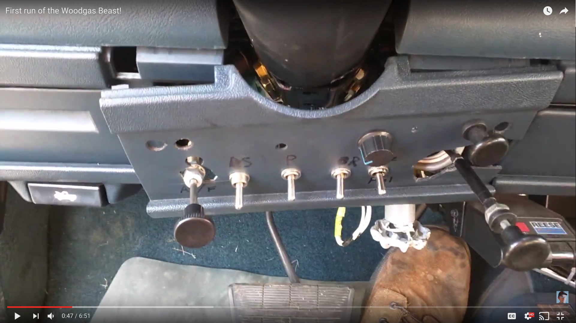
This is the thin dashboard plastic I’m dealing with, some of you may remember from my initial test drive video:
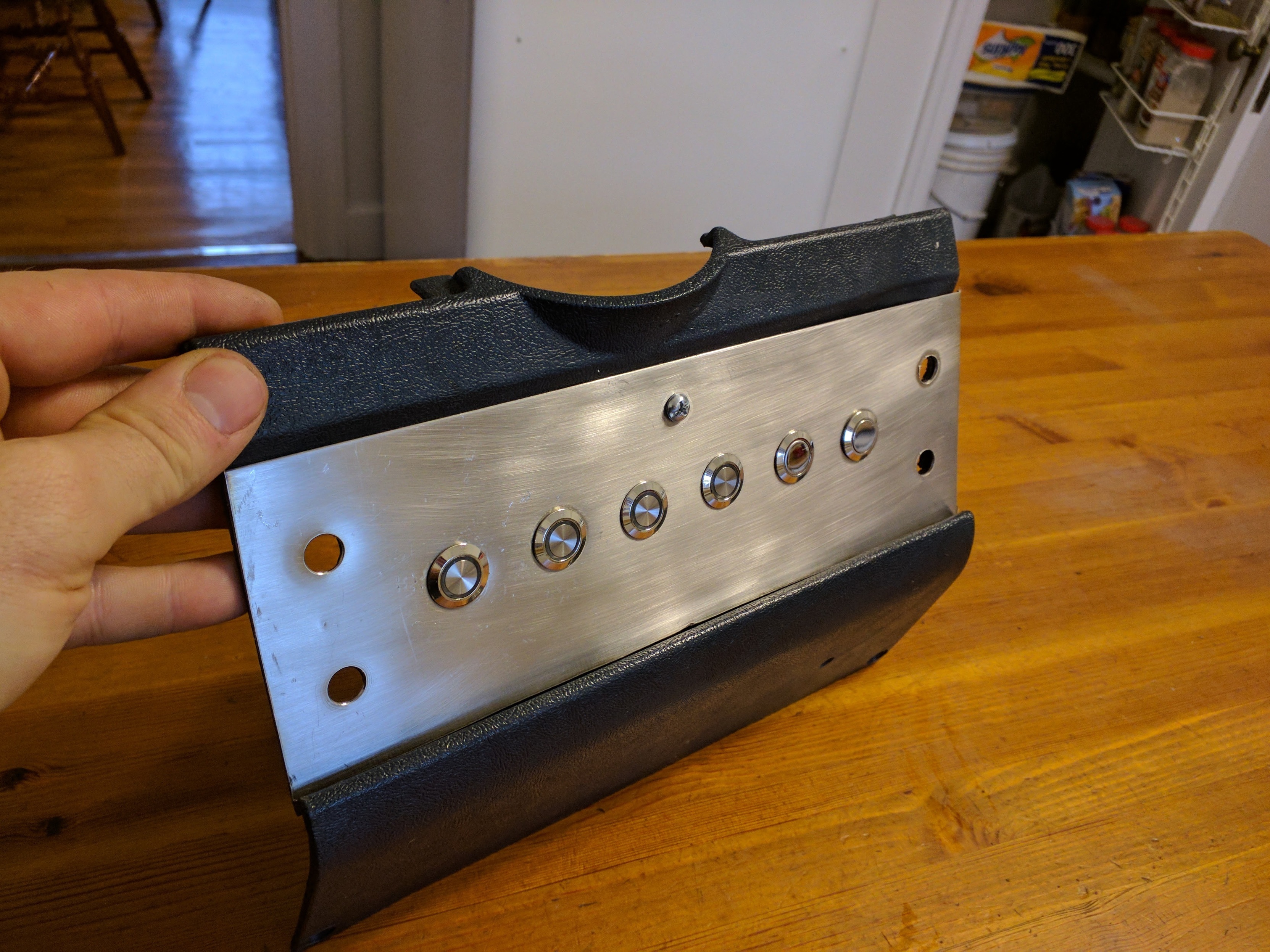
Notice it’s all been busted out where the stiff control cables go through. I have now repaired the holes via plastic welding, and made a nice stainless face plate for the new switches. Bonus points to the first person to tell me where the SS came from (it was free).
I have six buttons, and four control cables (2 gas, one air, one dist). Buttons left to right: Suction blowers on, pusher blowers on, reverse blowers on, hopper alarm hush, grate shaker, all blowers off. The first four have indicator lights. Blowers are blue, hopper alarm is red.
Here’s the backside. The plastic welding is ugly as sin. The big holes got filled though. It should be sturdy enough for a backplate for the SS.
Leftover pieces and parts of a display unit?
I see a lot of engineering in those pictures.
The eight ½ inch holes are punched to avoid hole saw run out or drill bit breakthrough bending.
The ¼ inch bolt in the center area keeps the middle section of the sheet metal from bowing out and serves as the grounding stud for the illumination of those push button switches.
The outer four cable holes maintain the sheet metal tightness at the corners of the plate.
Nice job regardless of where you got the metal from.
Step drilled Doug, that’s the magic of a Unibit. I will be using the bolt as a common ground, good eye.
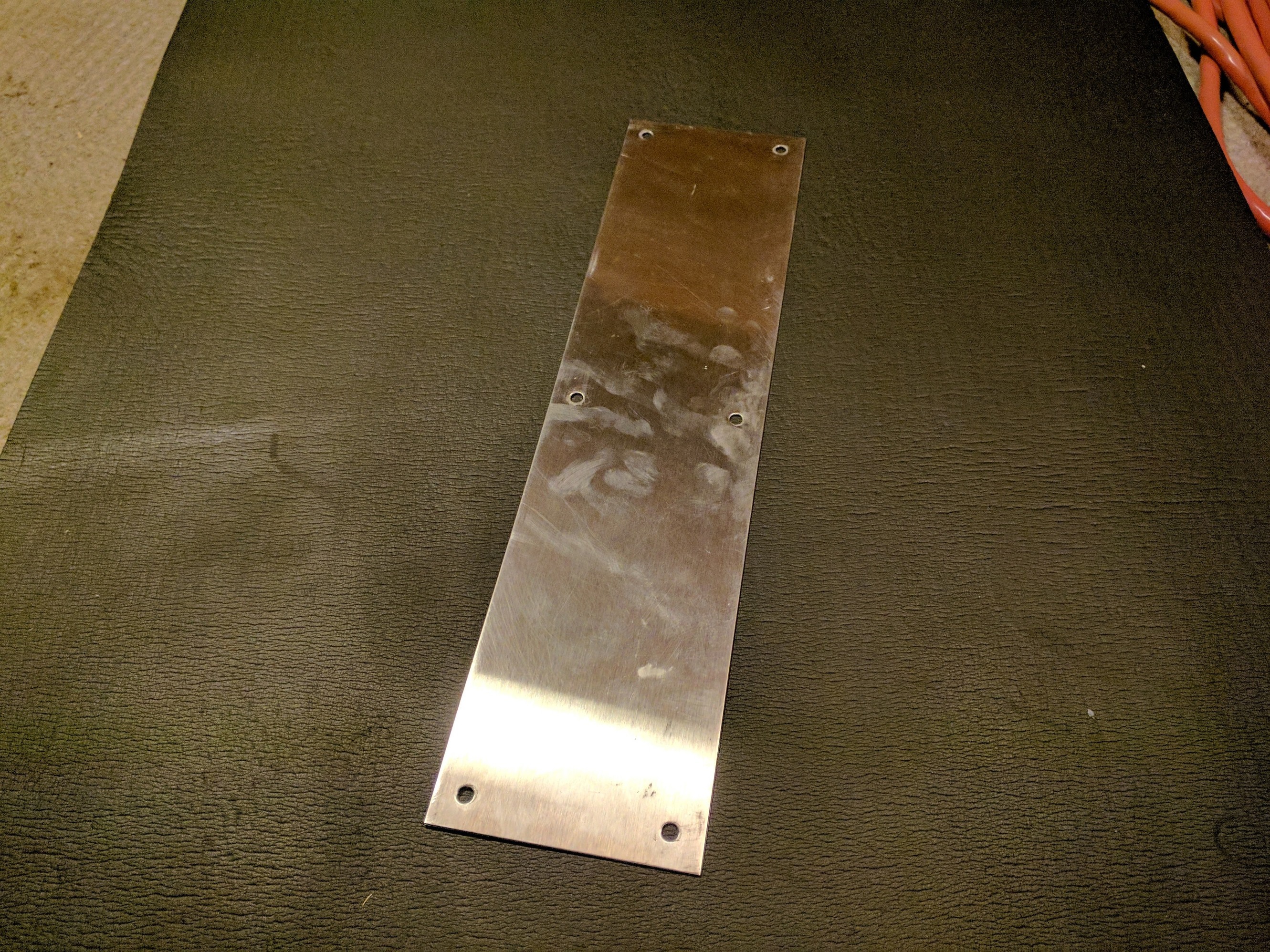
Not metal from a display unit. Much more common… I guarantee you’ve seen one, probably touched one in the last couple days…
A stainless steel sink
Nope… OK I won’t drag this out. Here it is before cutting. Door push plate, from a public restroom door.
Now what where you doing taking apart the bathroom door? 
Darn, I’ve got 4 of these still wrapped, found at a garage sale, solid brass for a buck apiece.
They came from work, they get replaced occasionally.
Scary to think of how much bathroom use it takes to wear out a SST push plate
Well, they lied to me. There are no internal resistors in these lighted buttons, they can’t take straight 12V. Pop! goes the LEDs.
I’ll have to order some more, and this time I’ll use external resistors. The buttons themselves are working fine, that bit of wiring is done thankfully.
Any update on this project?