Been awhile from me but I’m still at it.
Hi Steve Bowman! ![]()
In these few months coming up will be great for the woodgas community. I can’t disclose exact details at this time but I assure everyone here will enjoy what my Twin and I are about to accomplish. Really a life long dream and it’s become a once in a lifetime opportunity.
But in the meantime ive gathered enough materials to finally start building an all stainless Imbert style unit. Definitely an improvement from my first Gasifier over 10 years ago. Going with swappable hearth inserts and threaded nozzles that can be moved to two separate heights above the hearth. Plugging the unused holes ofcourse. The replaceable hearth inserts with the option for nozzle location will make this unit capable with the wide range I like to play with.
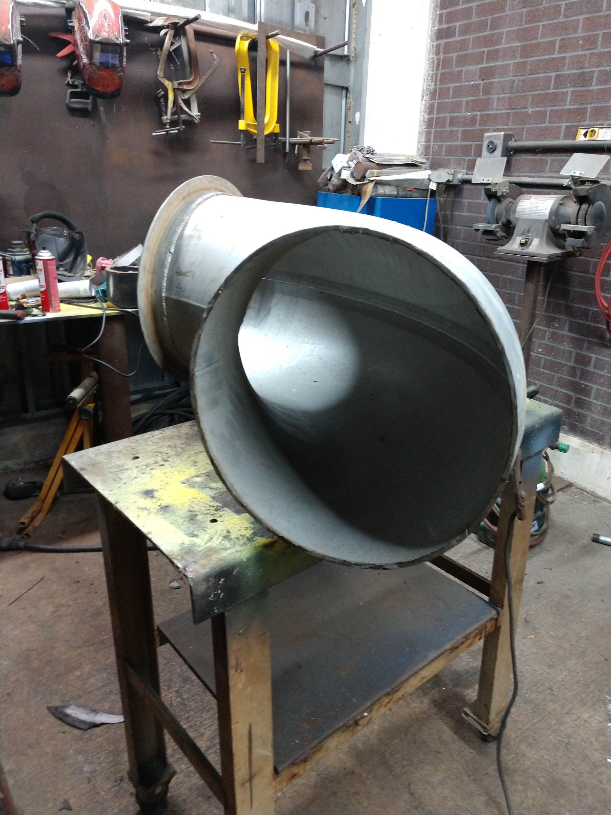
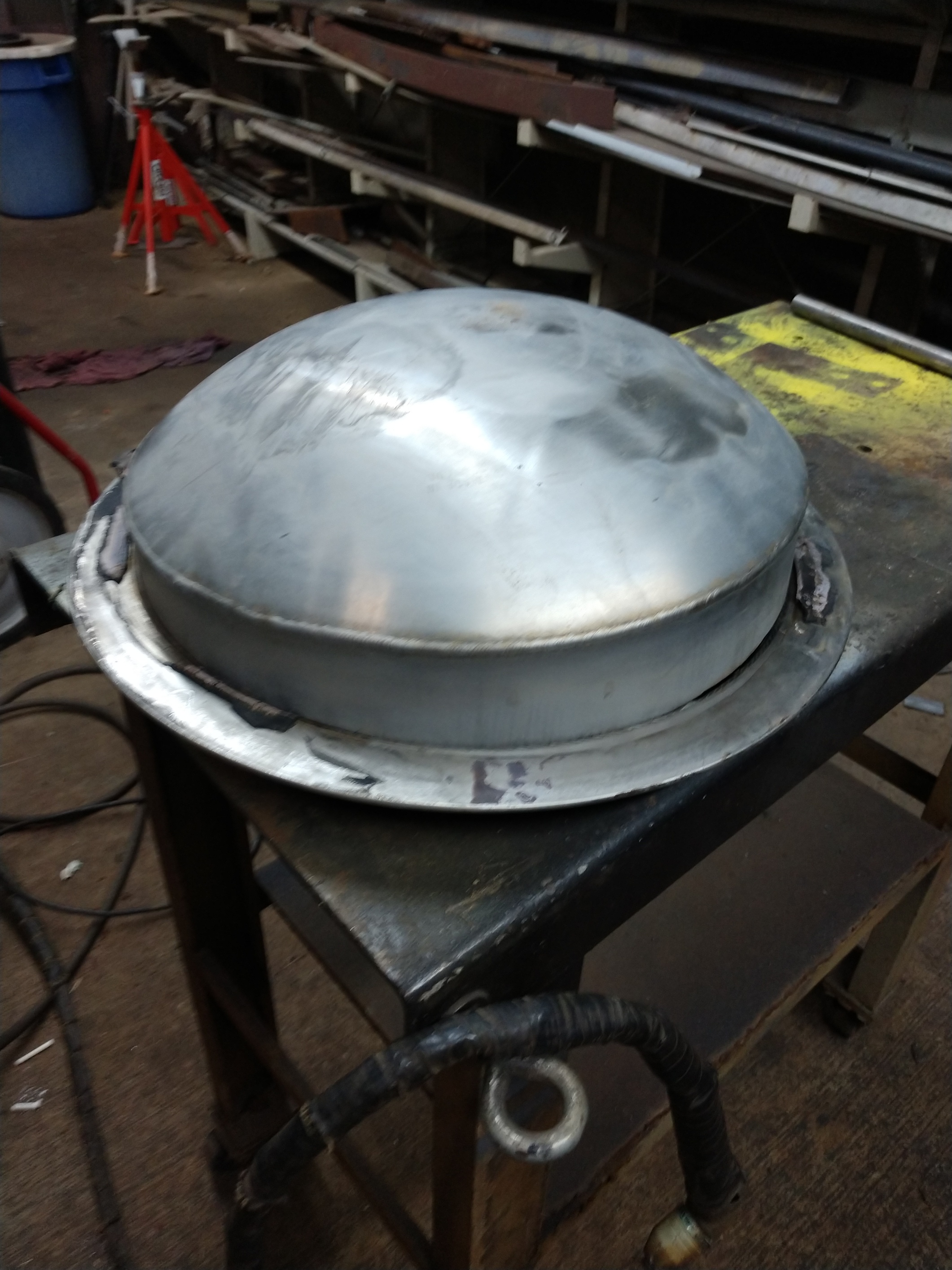
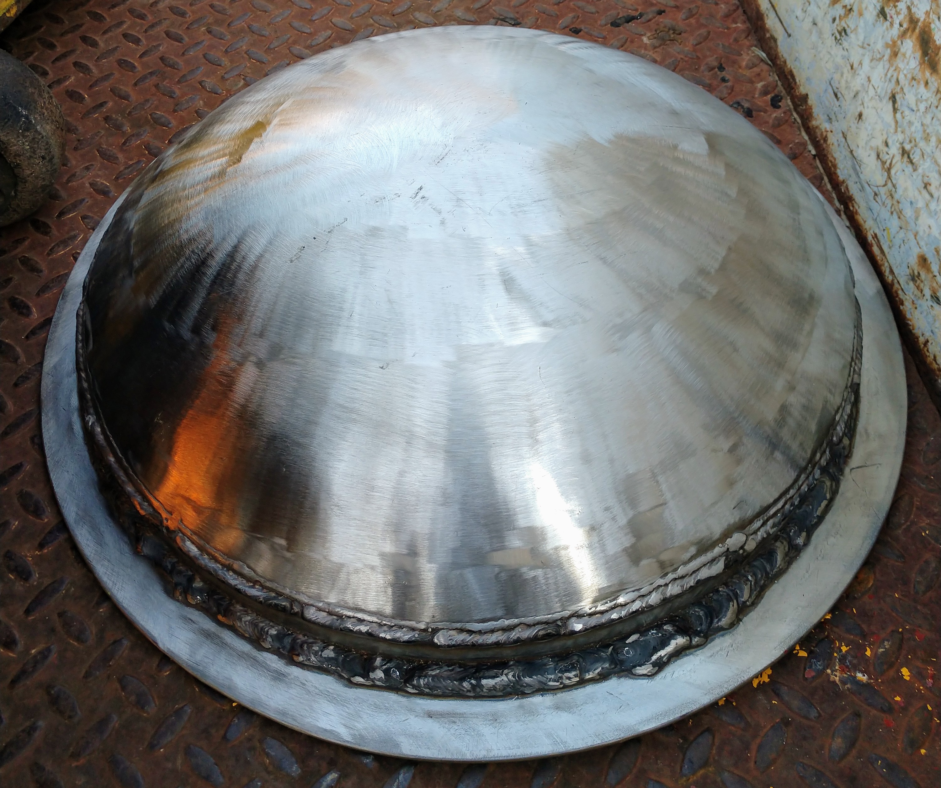
Outer gasifier shell will be made of 16" stainless tube. Grate is 3/8" thick. And all high heat areas like hearth and reduction tube will be beefy as well. I started with the top lid then currently welding up the bottom with the grate and grate shaft. Then fitting the critical pieces in-between like the pyrolysis zone, hearth and nozzle section. Many ideas inspired from the Peterson design but from the material selection I am subjected to its plans that match up well. I’ll supply photos soon but atleast here are a few for starters. Have a good one everyone!


Kyle,
I think about you every once in a while and wonder what you are up to—now I know. I’m looking forward to seeing your progress. You still have an invitation to bring your family and come by for a visit sometime.
Hi, Kyle!
Wish you all luck achieving a practical and easily modifyable build!
If setting the two nozzle levels on about 5% and 7% of the per second consumption volume level, you can later experiment with thoroid-blowing… I am following with interrest.
Max
Hi, Kyle!
Just for referenser, the record-Volvo, that made the 1000km trip
from Finland’s southern tip to the Norwegian Nord Cap, within
24 hours (1000 km ), has a 7% volume of the per second gas consumption.
This is the cut conical (60 degree) volume between the restriction and the nozzle-tip level.
Fuel size half a cigarette pack, for the Volvo.
Max
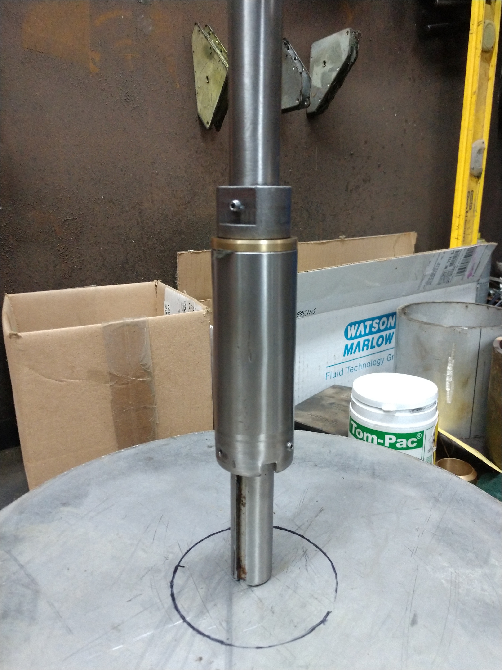
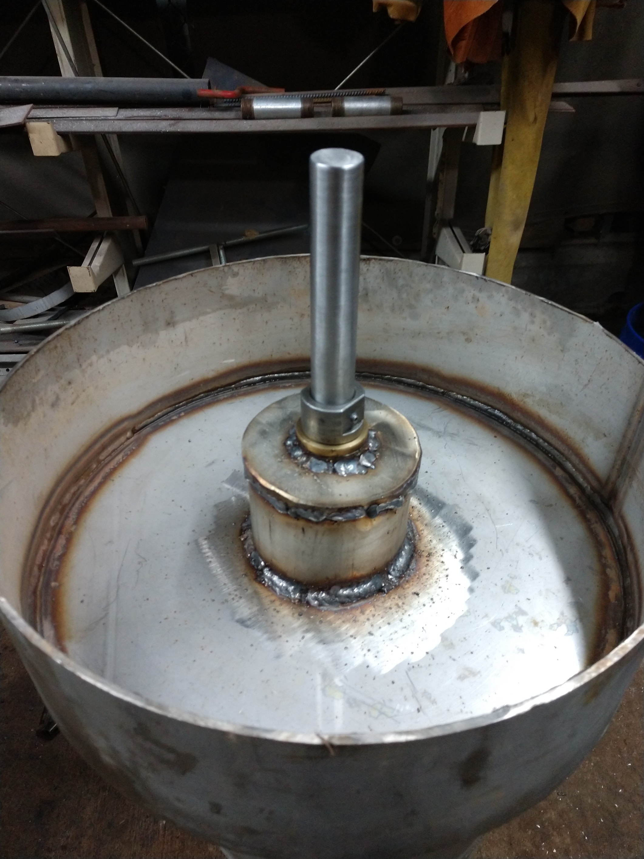
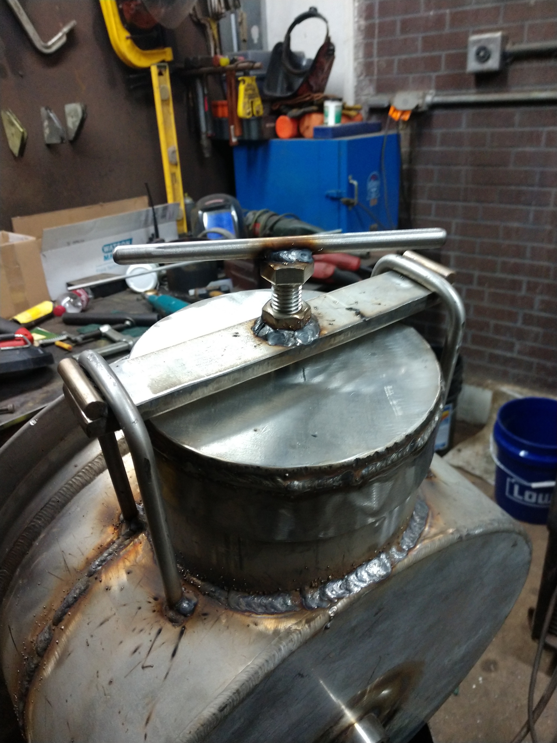
So now I can spend some time in the welding shed again. Got some things done. Turning out to be more of a ben peterson style than a traditional WW2 Imbert design I’d like to build. Dealing with the materials that the all mighty scrap pile has to offer. So here I am. Made a bushed and gland packed shaft support. 1" stainless shaft. Adjustable height with the lock collar. Going to take advantage of changing the grate to reduction tube height in the future. I want this unit to be wide in capability.
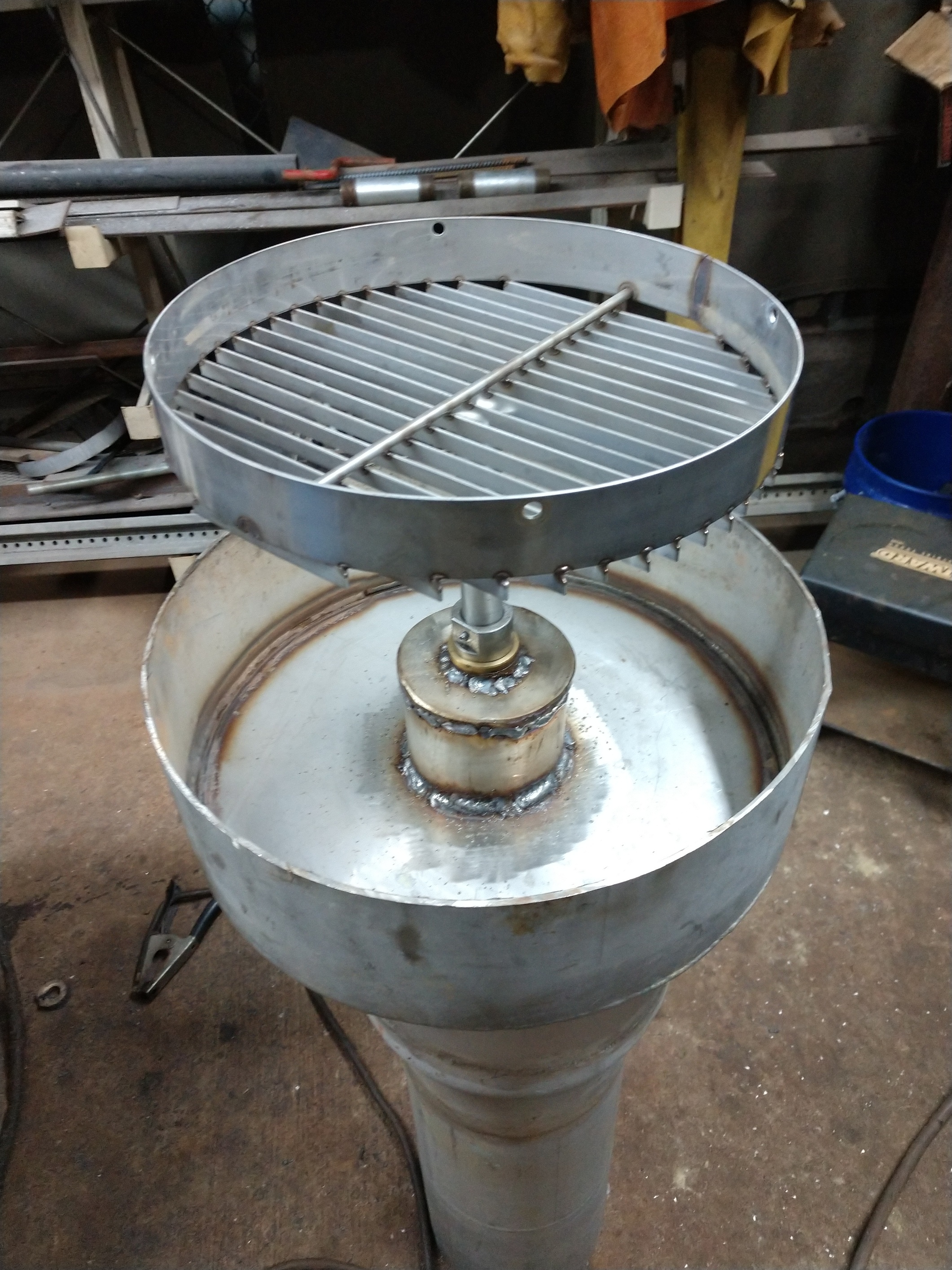
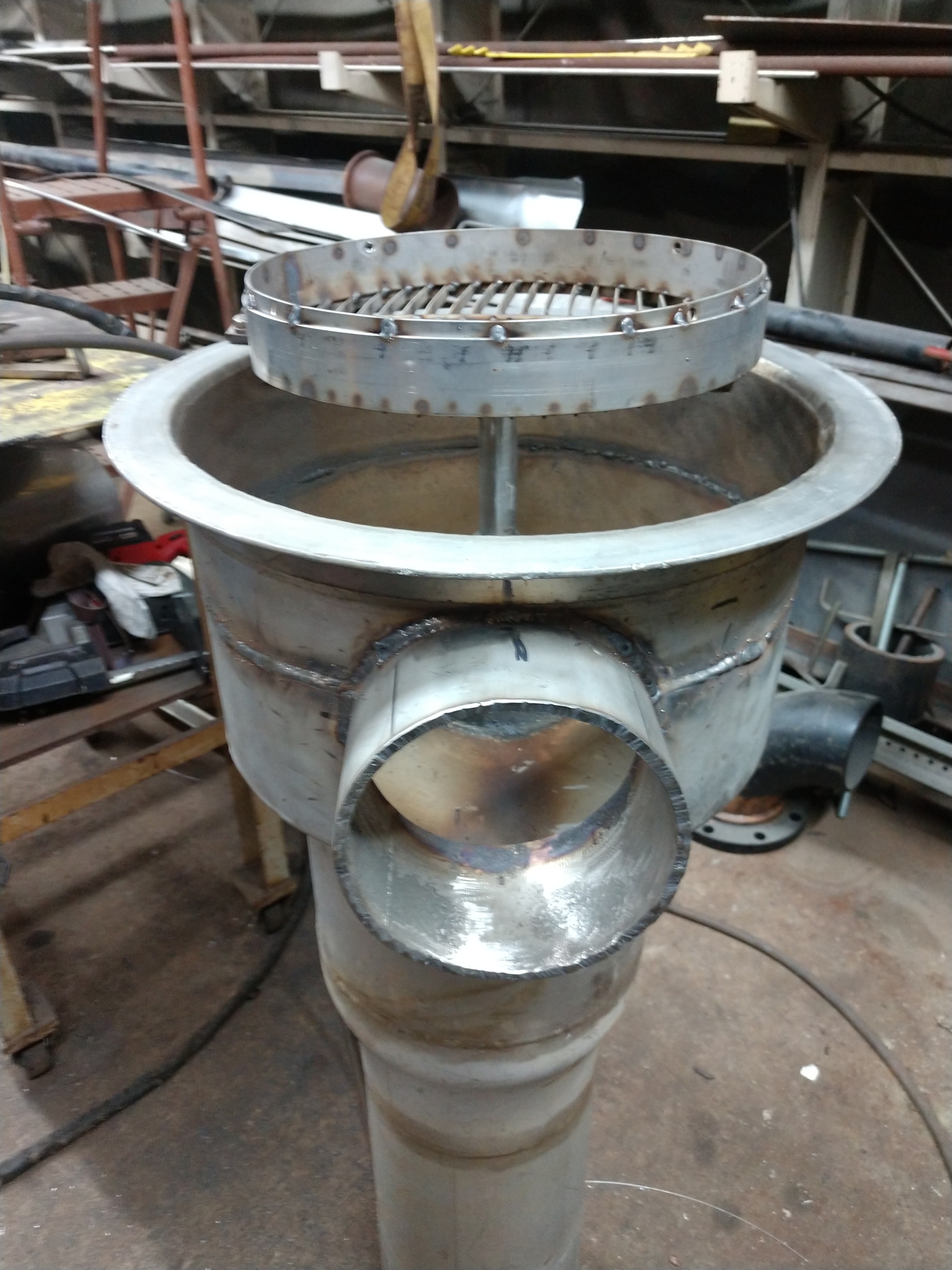
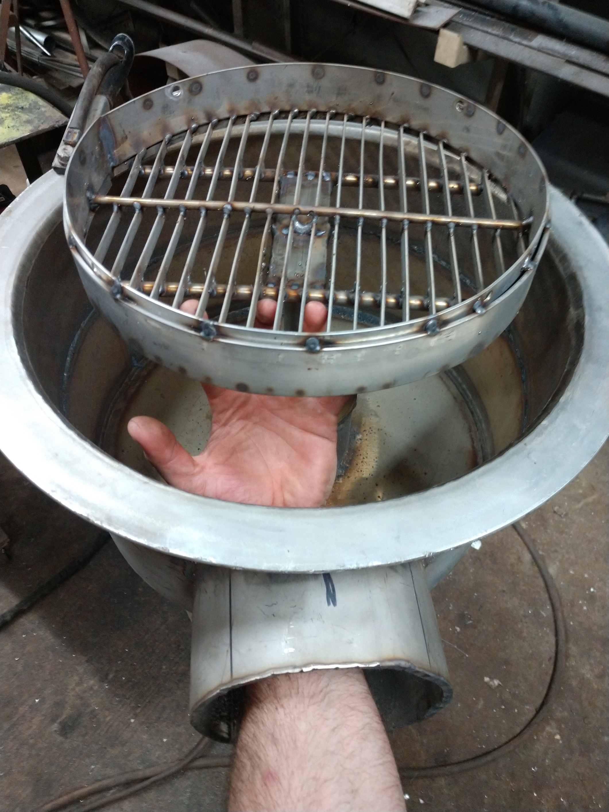
Pecking away. I decided to make this into flanged sections. There will be the bottom grate assembly. Hearth area and then hopper section. Thinking as I go along ofcourse so things may change. Cleanout is large enough to access the shaft lock collar to adjust the grate hight. Also to check clearance. I should have the cleanout cap made tonight. Headed back out to the scrap pile to shop haha
Wow that will be one hell of a heavy set up , least it will never rust away .
Yeah. Going to be mounted on a steel skid is the plan. Good thing I have a telehandler at work to pick up the finished unit haha.
Just might add some large diameter caster wheels on it once I get it to the house. We will see as always
Hi, Kyle!
29.9.2020
Elegant materials and decent welding!
But no pre-questions — no pre-suggestions…
No consumption specs — no proposals…
Still, observers role is also interesting!
Max
In regards to specs, thats still undecided. Going with a mantle that will accept multiple sized choke and reduction tube inserts. I’m researching on nozzle angle and definitely going to accommodate for a selection of nozzle placements. I have maybe 40+ stainless nozzles that I’ll drill out for my experiment in flow rates. Then match nozzle size to choke assembly when I want to swap out for a certain demand.
I’m always wide open for suggestions at any point during this build. Just can’t project any solid plans on my end due to the scrap selection but I’ll definitely make any suggestion a priority.
And I found that your overly kind words on my welding gave me a chuckle. The only good welds are the gas tight ones atleast lol. Next item on my list is the hearth assembly as I work my way up from the bottom.
Hi, Kyle!
29.9.2020
All measures in a certain “set up” are dependent on the existing or calculated cold gas flow. You just have to start from an actual motors max gas demand.
All calculations go in “counter-current”.
Actual flows in a hearth and passages are cold volumes times the “Kelvin factor” and actual passages / total passages…
Sorry, got carried away, no intention to lecture…
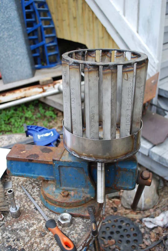
But, the grate “ribs” are unstable in the “heat-dancing” up and down!
Angle iron is a more stabil geometry. Valley upward, to collect protective ash.
No horizontal grate at all, just a well heat insulated plate or a flat insulation-pot (double bottomed) keeps the reduction char active further away from the restriction. Horizontal out-blow through a peripheral ring of vertical angle-irons welded (only) to a flat ring, bolted to the hearth-bottom periphery.
The flat double bottom can be fitted with a horzontal “midship” axel (shaft) allowing to tilt, scrap and rake out slag from two opposite sides. (perpendicular to this axel).
Have to stop, you are doing your choices…
Max
What’s your thoughts about me fitting a 3/8 plate ontop of the existing grate? The plate would be slotted and fit inside the diameter of the grate outer ring. Or should I just attach a whole different grate to the existing shaft entirely? The tilting concept is interesting. I’ll sketch some ideas on it tonight. I have no issue changing anything either. That’s why I have the flanged sections to change things up instead of welding everything together and being too late. I appreciate your input so keep adding if you want. I’m listening 
So reading up on one of your suggestions from 2017 on grate design. You’ve clarified to another member that using angle iron in the “V” orientation is best to reduce the heat transfer to the grate. The valley of the angle iron retains a layer of insulating ash. Atleast that’s the way I understood it. Makes sense and I have a stock of stainless angle to make a new grate. So that’s on my list to do next. Also to check my selection of material to get an idea of a tilt design.
Ill draw up some of these ideas before I dive into it. I’d like to see if you can guide me in the right direction since I’m a visual learner/notepad fabricator. In the meantime I’ll thumb thru the forum
Now I have a grasp of the tilting design. This is completely achievable for me as well. I have ideas to sleep on tonight.
Hi, Kyle!
30.9.2020
OK, things have appeared some time ago…
But now I hope you will concentrate on the project at hand.
The 2017 vertical angle grate does not have the right proportions for your project at hand.
You have started a build including a horizontal grate.
To improve this design choice, I suggested to change the thin “blade” grate bars to sturdier
V-profile grate bars.
I hope it will bend less and work more reliable.
Still a horizontal grate.
Then I suggested a second style of reduction where the glowing gas and char from the restriction ring (opening) broadens out horizontally over a flat insulating plate.
The height between the restriction ring (opening) and the insulating plate would be 0,25 – 0,33 restriction diameters. ( to maintain high speed )
This insulated, double plate bottom with mineral wool in between would have a height (thickness) of 0,2 – 0,4 restriction diameters.
This Flat “bucket” is hanged up with an “amidship” horizontal axle (Shaft) , maneuverable from outside (gas-tight) through the ash-chamber. ( for tilting, scrapping, raking slag on either side; the sides are opening under the edge of the angle-iron fence when tilting the insulation bucket)
The gas from the restriction rushes out through high-glowing char horizontally between the oxidation chamber bottom and the double-bottomed insulating “bucket”.
The char is stopped from blowing out by a “fence” composed of vertical angle-iron stumps welded in their upper ends to a flat ring, bolted from below to the horizontal bottom of the oxidation zone.
Use smaller angle-iron profile ~15 – 20 mm.
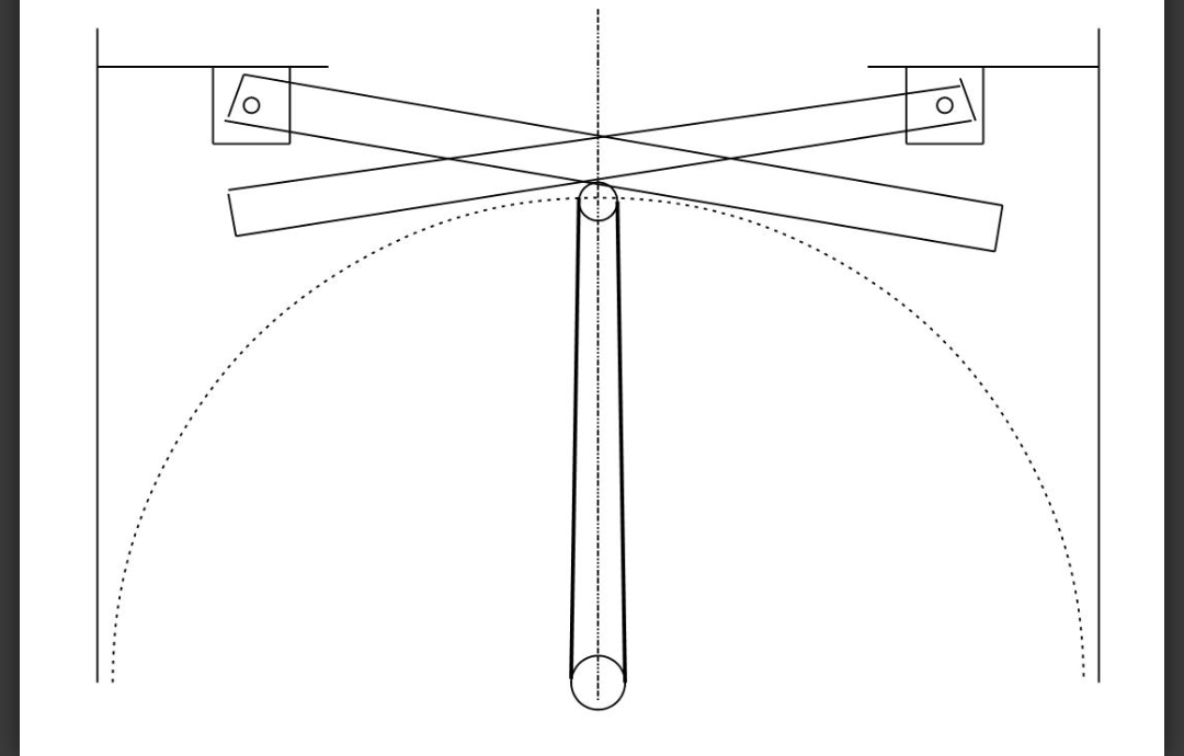
Don’t start cutting or welding before you have a confirmed drawing on the site! By your hand!
Your sketch or drawing will save you unnecessary work, as it can eliminate eventual misunderstandings about sizes and proportions,
that can get a “last-minute” correction before work starts…
Max
Hi, Kyle!
1.10.2020
I am waiting to comment / correct your working drawing…
Max
I’ve kept you in my mind. Haven’t been able to get back to the weld shed but I’m currently scouting ideas on here before I draw up anything. Put my but in a chair and do the research since I don’t like to seem like the guy to EXPECT easy answers from people who put in the miles on their own. I’ll keep you posted
Hi, Kyle!
8.10.2020
Flow calculations start with “Cold & Empty”…
What does “put in the miles on their own” mean?
Max