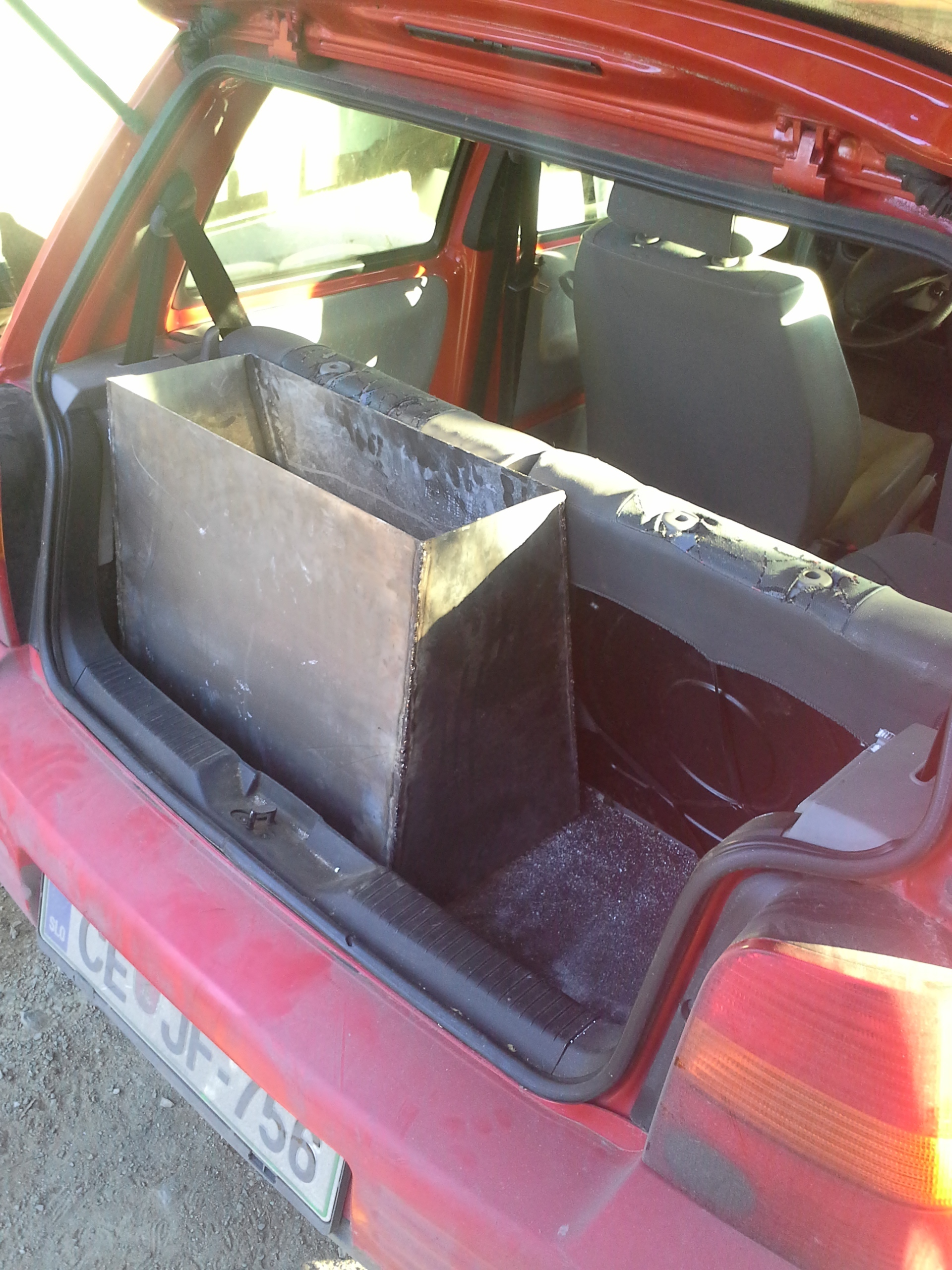
It has been a while since my last project so i finali decided to try and power my thrusty old Seat arosa 1.0 on charcoal.
The goal was to make a gasifier that wuld not be a gigantic nuclear reactor looking thing on the back of the car mainly becouse of Slovenian strict police law that wuld almost certanly put me behind tha bars for that.
I am experimenting a bit here so I am in need of some advice. I have never operated an engine with more thain 5hp on woodgas. This one has 50hp.
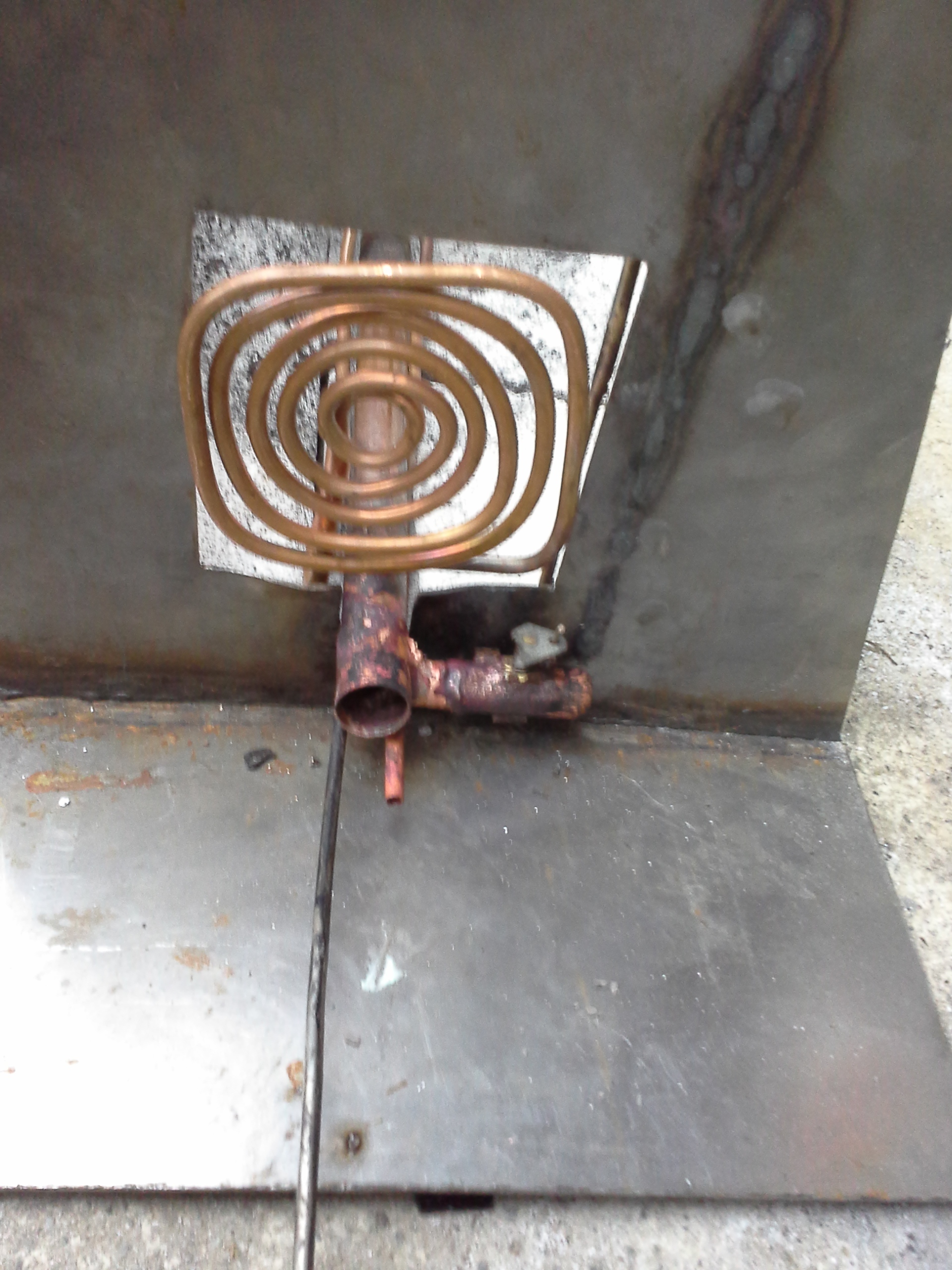
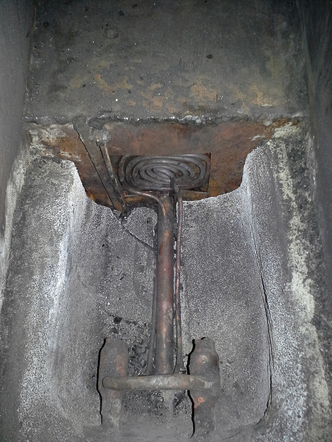
My main consern is the heart seen on this picture:
Now for he question; the lengh from nozzle to the grid is just 20cm as I had very limited space. Do you think that will be enough for the 1l engine? The core will be steam an exhaust temperated so i realy hope this works!
My apologies, but I have no idea what you are doing. I may have missed something in the past. Anyway, would you bring us up to date on what we are looking at. Is it going to run on wood or charcoal? What is the object of the water? If it is anything like what I am thinking those copper pieces will melt. 20 cm to the grate— where would that be?? Does a hopper go on top of what is shown?TomC
PS Very nice looking workmanship.
Hi Kristijan, maybe a cross draft! 20cm is about 8” and that seems kind of close to the grate BUT I never used a nozzeled cross draft before. I hope others chime in, so to speak…
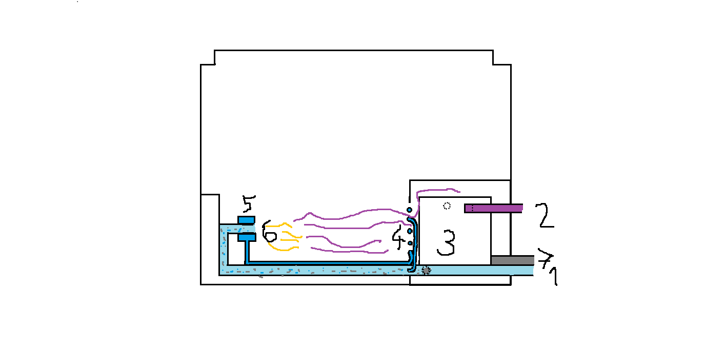
this is the big idea:)
A crossdraft charcoal gasifier. The copper pipes and nozzles are all double walled and watter will cirkulate in them to cool them down so i think that shuld be ok.
the nozzles and the grid seen on te pic
It ran great on a small fan without exhaust return but I dont know what will happen when i hook up a 1l engine:)
I think Gary and others had good luck with copper nozzles but I don’t fallow that end much. My big concern would be running it inside of the vehicle because of CO poisoning.
CO poisoning is high on my list of things I dont want to happen to me so care is taken to take the risk away. The gasifier will be isolated with 2cm of rock woll and coated with a nother sheet of steel so i hope that will take care of any potential leaks and heat emissions. The air intake will alsow be from the outside and a CO alarm placed in the car.
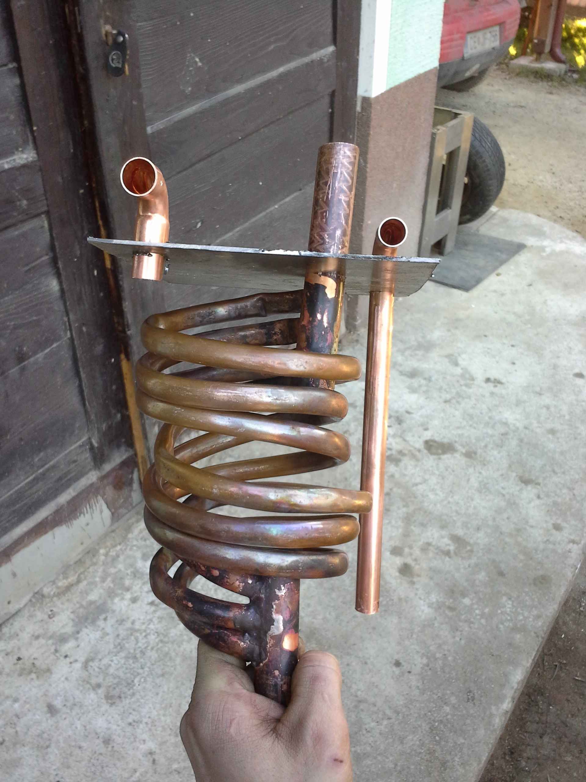
I like your hearth and double-walled water-cooled copper tuyeres. I assume the coil is your steam generator and is heated by exiting gas. It looks like the copper ring supports your nozzles and provides a path for steam delivery? If I’m guessing right then the biggest problem is not the distance to the grid, but the size of your gas outlet. Looks like 25mm? That may work, but I would want a 50mm supply hose to the engine. Smaller may be OK on your 1.0L. Also, if possible build a new wide open intake manifold for unrestricted gas flow to the engine. My 2.4L Toyota ran very well on a tiny 5 gallon reactor, but at 3 miles to a gallon of charcoal I could only drive about 7 miles before the charcoal level exposed the reduction zone and started overheating. I added a 5 gallon hopper on top to extend range to 20 miles. I used charcoal made from pellets (about 8X8X15mm), But a little larger is probably OK. Keep the reaction zone temp between 900-1000C. If you can see into the reaction zone, add enough exhaust to cool it down so that you can see the shape of the individual pieces of charcoal. I’m curious to hear how about your filter and other details. Very interesting!
Spot on about all but the outlet. The coil acts like a grate so the outlet is in fact 11x11cm. The pipe on the bottom is in fact the intake. I might have to cement it to protect it from the heat.
i didnt quite understand what you ment with that culd you explain?
Very usefull info thanks so much!
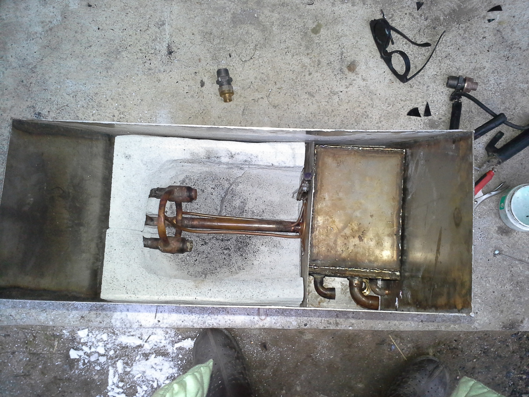
I am experimenting on something with the gas cooling and cleaning but lets keep it as a secret till its done but for now here is a litle teaser:)
I apologized with my first post but I guess that didn’t qualify me for any lack of knowledge of your system. Again I apologize.
Could you possibly draw up a sketch and label what is going on. I have found that the old adage a picture is worth a thousand words is true.
Looking at the nozzles, it appears to me that you have run this set-up. I will wait for more information, but I will say, I have a full size pickup running on woodgas and I am very interested in running a small vehicle on woodgas. Be it wood or charcoal. A German runs an Opel on wood and I saw a gasifier on some small Russian vehicle ( Yugo ? ). Here a fellow ran a 1000 cc Ford wagon on wood and I have all of his info. So please keep us filled in TomC
Talking about small vehicles. I like this russian Vaz/Lada, not charcoal but…
I wish I could understand what he says.
First video is system overview. Second one is startup and test run.
Hi Kristijan,
Welcome to this group and we will be anxious to see and learn from your experiences. (chalk another one up for charcoal OK, you are making a cross draft charcoal gasifier. Cold water will enter the copper ring that is attached to the two supports. The combustion air intake is not visible in your picture or drawing but let me assume this air will pass through the copper ring. Correct? How large is your air inlet? For a 1liter engine it had better be at least 2.5 cm, Will you be able to see the burning charcoal when the unit is in operation? Using steam is great because it displaces nitrogen and adds oxygen and hydrogen to your chargas BUT. It also cools down the oxidation of the charcoal and when this reaction drops below a certain temperature, your steam will no longer split into O2 and H2. Pulsing the steam is the method used to produce water gas. The gas is obtained when air is alternately blown in to fan the fire up to 3000F and then steam added to produce the gas. My concern here is you will run the fire too cool and end up with lots of condensed water in you heat exchanger. This means some way to regulate the amount of steam getting into the oxidation zone.
With a steam setup, I do not see a need for exhaust gas return, unless there are issues with freezing water. But, without water in your system, the copper tubing will melt away, probably in your first serious run.
Let me assume the coiled copper pipe that makes up the gas exit grate will also be filled with water. I like this idea. A steel screen with 1/8" mesh will keep some of the larger charcoal pieces from being pulled through,
Try to get as much height to your charcoal container as possible, This will give you longer run times. Also be VERY diligent about air leaks into the gasifier, You want all your air to come in from the air inlet opening. Let me also assume you will have a valve there to shut off the air inlet when you shut down the generator,
Also a question on the size of your chargas outlet. What size is it? To avoid restricting chargas to your engine, this outlet should be at least a little larger than the air inlet into the carburetor. You cannot go wrong by being too big, but you sure can starve that little engine if you go too small. Running on chargas is a humbling experiance when comparing it to the performance of your machine running on gasoline, Give your engine as much chargas as it wants!
Enough for now, Happy New years to everyone.
Gary in PA
OK, hopefully the size of the two nozzles combined is close to the same as the 25mm inlet. I’m guessing that it may work even though the double wall water jacket restricts the air flow on its way to the nozzles.
Now about the intake manifold, On my engines small and large, I remove the carburetor. On the toyota I was able to open up the inlet area where the carb used to be and added a gas/air mixing chamber where the carb used to be. On my MGB, the manifold was combined with the exhaust manifold to preheat the entering fuel. This is bad for charcoal gas which needs to be cool. Also the manifold had sharp bends restricting the flow. So I replaced the intake with an older version that is more open. I use a throttle body from another vehicle for the throttle which is placed between a baffled mixing chamber and the new manifold. Some research has found that good gas mixing and smooth flow of gases into (and out of) the engine can squeeze up to 25% more power out of producer gas. Because of driving conditions and variations in gas quality it is best to have control of both air/fuel mixture and timing while driving in order to maintain maximum power. Keep up the good work.
Wow Kristijan; When I asked for a “drawing” I was thinking paper and pencil. That is an excellent representation of your design. I assume that was done by Sketchup. I never got a handle on that. Any way, now I think we all have a better idea of you plans and as you have seen, you are getting some very good information back
A little more detail on what is going on around No 3 the cooler. In one photo I see two lines coming out on the side at the bottom. Is that for water circulation? And as someone else asked what about No.7
Thank you very much and I’m watching with great interest. You are working in an area where I’m sure most of us have never traveled but the ones that have will chime in. TomC
JO you did it to me again. I brought up the 1st two videos and an hour and a half later I am responding. That is really what I would like to do. I forgot to mention Don Mann’s Geo Tracker is one I love but he has a very large and complicated gasifier.
Kristijan; Do you understand what is being said in these two videos? If you do could you explain or possibly “draw” what his system is made up of.TomC
The air flows in the pipe on the bottom of the heart in the opposite direction as the gas flow thru the heart. It thain makes a 180deg. turn and comes out thru the jacked nozzle.
The water comes in the nozzle jacket to cool it down and then goes partialy vaporised under the heart in the coil/grate from where it is united with the air/exhaust mix.
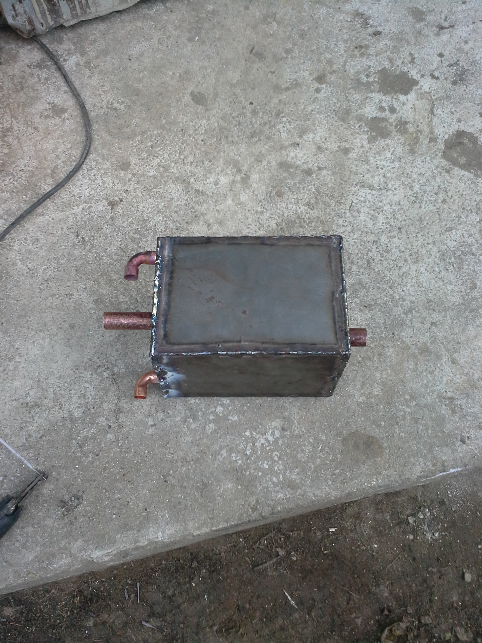
The plan is to set the water injection just so that the nozzles stay cool and there is no condensation in the gas at a normal engine speed and in case the temperature starts rising up (due to higher gas demand or what ever) a nother experimental component kicks in. I present you automatic exhaust gas valve:
It has a bimetalic strip (partialy seen on the right of the coil) conected to a buterfly valve seen under the coil on the right. None of the pipes were yet conect on this pic. The big 22mm pipe is air intake and the small copper tube is water intake.
I have tryed to pulsate steam/air on my previous generators but it just doesent seem practical for an engine use. Great for some other aplications thugh!
I sure hope its big enough. It is a 22mm to 3x10mm to 22mm. The coil is submerged in cooling water. The whole setup is 1m of pipe all together (uncoiled) so i sure hope this will not starve the engine. From here forvard will be a 4-5cm pipe to the engine. I allso have to point out that the gas is already cool in about half way thru the coil so the volume of gas and therfor gas flow shuld be lower.
the jacket shuld not restrict any gas flow. It is simply a pipe around a pipe. The nozzles are both 18mm so I expect no problem here.
Hehe just Paint realy:) no3 is the coil above submerged in water. no7 is exhaust gas return.[quote=“TomC, post:18, topic:2181”]
Kristijan; Do you understand what is being said in these two videos?
[/quote]
Well the thing is that eaven thugh I dont speak Ukrainian the Slavic languages are so similar tco each other it realy isnt hard for us to understand each other:) Its great beaing Slavic;)
He says gas only has around 60*C once it comes out of the cyclone. Alitle low dont you think?
He has a intercooler in front of the car radiator.
He has a three part cyclone-large partical-fine partical filter system and fuel consumption is i think 28kg/100km. Other he didnt say
Another question for you guis; what kind of water consumption shuld I expect? How do Iset the egnition timing?
I wuld also like to take the opertunity and thank you mr. Gilmore for the video on youtube on making and procesing charcoal. Made a 200l bach today and got 7.5kg of fantastic oak and chery charcoal out of it in just a few hours. A very fast, easy and economical proces!


 OK, you are making a cross draft charcoal gasifier. Cold water will enter the copper ring that is attached to the two supports. The combustion air intake is not visible in your picture or drawing but let me assume this air will pass through the copper ring. Correct? How large is your air inlet? For a 1liter engine it had better be at least 2.5 cm, Will you be able to see the burning charcoal when the unit is in operation? Using steam is great because it displaces nitrogen and adds oxygen and hydrogen to your chargas BUT. It also cools down the oxidation of the charcoal and when this reaction drops below a certain temperature, your steam will no longer split into O2 and H2. Pulsing the steam is the method used to produce water gas. The gas is obtained when air is alternately blown in to fan the fire up to 3000F and then steam added to produce the gas. My concern here is you will run the fire too cool and end up with lots of condensed water in you heat exchanger. This means some way to regulate the amount of steam getting into the oxidation zone.