Charging a DC bank with a DC generator

Hello All,

Got a question I’d like to pose. I do need to frame up the operational environment to clarify what I am asking. Please bear with me.

I have a PMG DC generator head. The head is a Werner Power F60AD, (Chinese manufactured), that I got from CGG.

It is rated up to 58.5 vdc @ 100amps. Right now it is connected to a 22hp Iseki, (Bolens knock off), tractor pto via a belt system that gives me some control over the RPM range. The gen head has max RPM rating of 3000.

My system has a 48vdc Nickel battery bank. Nickel cells are nominally 1.2vdc. Connect 40 in series to make a 48vdc bank.

I have run the the head and applied a charge to my bank for a short period of time, (5 minutes), and it appears to work.

Current and voltage measurements during the run were what I expected. The gen head did get hot to the touch. Which worries me.

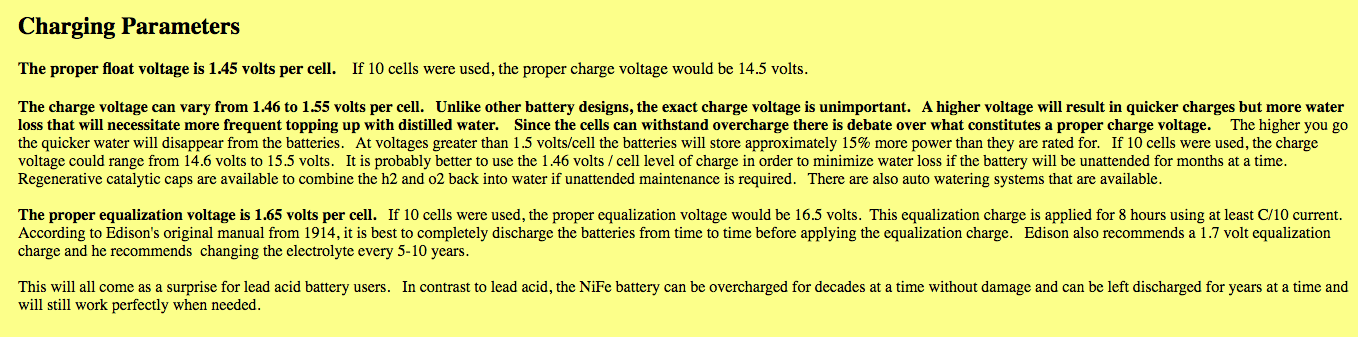
Fully charging or equalizing my battery bank means that I have to drive the bank voltage to 70vdc, (40 cell bank @ 1.7vdc per cell), and hold it there for an extended period of time.

That gen head can push a maximum of 58.5vdc. With 40 cells in series, the head will only push enough voltage to raise the cells to 1.46vdc each.

The obvious answer is to lower the number of cells under charge to match the desired end point cell voltage to the gen heads capabilities.

In this case lower the number of cells in series, under charge, to 34. 58vdc / 34 = 1.70vdc per cell.

Doing this significantly lowers the resistance of the battery bank, and leaves some cells un charged. In my case 6 cells.

Here are my questions.

1.) Do you think charging a battery bank with a starting voltage of 34vdc, with a 58vdc generator is a problem?

2.) Can I lower the number of cells under charge to 20 cells, (nominal starting bank charge of 24vdc)?

The reason I ask about 20 cells is a physical one. From a cabling perspective it would be very easy for me to split my bank from being 1 40 cell bank into 2 20 cell banks.

And IF charging a 24vdc bank with a 58vdc generator is not a problem then I can completely equalize my entire bank. It just takes longer.

Thank you for your time and attention.

1 Like

All I could think of is a submarine

The Oberon class was a ship class of 27 British-designed submarines operated by five different nations.
Submarine batteries are made up of many individual cells. My submarines (Oberon class of the 1960s-1990s) had two lead acid batteries containing 224 cells each with a nominal voltage of 440 volts… The cells were rated 74.20 ampere-hours at a 5 hour rate (nominal voltage of each cell was 2.2 volts, and each cell weighed over half a ton. There were 18.5 gallons of electrolyte within each cell. The Oberon class had 2 Admiralty Standard Range 1 diesel engines that turned a generator each. At sea, the normal charging rates varied between 200 amps to 1400 amps each battery depending upon the speed of the submarine. When delivered, the batteries were rated as 7200 A/hr batteries so charging them to a full operational charge would take anywhere from 36 to 5 hours at the charging rates I just mentioned. About 15 years after the boats had been in service, the batteries were replaced with Varta batteries, and they were rated at 9600 A/hr. Thus, using the same charging rates, it would take 48 to 6.8 hours to charge them to a full operational charge.

The submarine has two batteries, each comprising 224 2V cells (type D7420) giving a nominal 440 V output. One battery is located underneath the crew accommodation compartment, and the other under the control compartment. Each battery has a switch circuit in the middle so it can be split into two banks of 112 cells. The cells are designed to deliver 7420 Ah over a period of five hours. All steelwork within the battery compartments is lined with rubber to protect the metal from attack by acid, and also all conducting material is insulated to prevent risks of electric shock. Waxed timber is used to make framing and crawlways to access the batteries and support them because of its resistance to acid. The battery compartment has a sump to collect any spilled liquids. Each cell weighs 1,120 lb (510 kg) and contains 18.5 gallons of electrolyte. Cells are held tightly in place with wooden wedges to prevent movement with the boat. Each cell has four connector bolts to each electrode and an agitator pipe which bubbles air through the cell to ensure the electrolyte remains mixed and uniform. Cooling water is fed through pipes attached to the electrode connectors to prevent overheating and the battery temperature is monitored.

In operation, each battery is charged until the voltage reaches 560 V, then allowed a further hour’s charging. Fortnightly, it should be allowed 5 hours’ charging after reaching 560 V to ensure a maximum charge is reached. Every two months, the battery should be given an equalising charge of eight hours to ensure all cells have reached their maximum. The battery is designed to operate with a specific gravity of the electrolyte between 1.080 and 1.280. Initial charging current should be around 1650 amps for s.g. below 1.180, 1250 A above 1.180, falling to 280 A when charging is complete. At a voltage around 538 V, the cells begin to give off explosive hydrogen gas, so the applied power is reduced during charging to keep voltage below this value until current falls to 280 A, which is then maintained while voltage is allowed to rise until the requisite voltage and charge time are reached. In an emergency, the charging current can be raised to 2000 A. To maintain overall capacity, batteries need to be completely discharged over a five-hour period once every four months and then completely recharged. The battery compartments are sealed to prevent gases escaping into the submarine, or salt water entering, which inside a battery would cause the release of poisonous chlorine gas. Ventilation fans are used to extract hydrogen released by the cells and catalytic converters are placed strategically through the submarine to remove hydrogen from the air by recombining it with oxygen to form water.
Each of the two propellers on the submarine is connected to a 3000 bhp DC electric motor. Each motor is designed with two separate armatures, in effect two motors in the same unit. Speed of the submarine can be varied by connecting the batteries and armatures in different series and parallel combinations. Slowest speed is obtained by connecting both batteries in parallel, thus supplying 440 V, across all four motor armatures in series, thus applying 110 V to each (‘shafts in series’). Next, the batteries in parallel may be applied across the two motors in parallel, with their armatures in series (‘group down’). This applies 220 V across each armature. Third, both batteries are applied in parallel across all four armatures applying 440 V to each (‘group up’). Finally, the batteries can be arranged in series so as to apply 880 V across all four armatures in parallel (‘batteries in series’). Each armature also has an associated field winding which is separately supplied with current which may be varied resistively, providing further speed control (maximum 35 A).

2 Likes

Thank you. That is a helluva post and system. Custom designed and purpose built.

What I am using is “niche” but still somewhat off the shelf.

I do wonder …

Each battery has a switch circuit in the middle so it can be split into two banks of 112 cells.

Did charging operations ever occur when the L.A. bank was configured to be split?

How does a dc generator react when the resistance of the load is halved?

Once again thank you.

1 Like

I do not really know anything . I have 16 trojan l16 batteries in a 48 volt system . It is on standby . it has 50 watt maintainer charge . I created a paper form for filling batteries . Build the system you require , Do not add any extra switches . Maintain the system .

1 Like

Hi Mark,
Could you provide a bit more information on your “Nickel” cells ? coz one nickel cell is not same as the other nickel… (Ncd or Nmh do charge different )
You will probably end up with temp controlled charging / trickle charging and a good charger controller is to be found for your needs.

Battery’s ain’t always easy…

3 Likes

http://wernerpower.com/application/8-en.html

1 Like

they might have a suitable controller

1 Like

Thank you Koen

My production bank is 40 Changhong 1000ah Nickel Iron cells. They are cabled in series to form a nominal 48vdc battery.

Here is a link to the users manual.

These cells are currently charged by a 4.5Kw PV array on an active tracking mount. My charge controllers are Outback MX-60’s.

Yes. That is the generator head I have.

I guess my question is really about how a permanent magnet generator reacts with a load?

Is there a minimum required load?

1 Like

Those NiFe battery’s are great

You can connect your DC generator parallel with your solar panels and charge over your charge controllers.
Or direct to the battery pack, depending on what circuit the gen head still have.

2 Likes

I was thinking the same thing use a solar charge controller to handle the logic.
With those batteries the good news is over charging or charging too fast will basically just increase the outgasing and require you add more distilled water. They are a very tough battery. I wanted to go that route myself but I couldn’t justify the cost.

1 Like

Thank you,

I am extremely happy with my cells. I am more concerned with the generator head.

If I re-cable my bank to be 2 - 24vdc parallel banks and try to charge them with this Werner PMG generator head … Am I going to damage the PMG?

How this all ties into gasification and why am I asking here is …

I have built a Koen style charcoal retort. I have built a GGilmore style charcoal gasifier based on a 50 gallon drum.

These are to fuel my tractor in part. It is a diesel so I know I have to have at least 20% liquid fuel for lubrication purposes. The tractor in turn used to power generator heads, water pumps, etc.

Right now we are in the monsoon season, slalom dodging typhoons. Everything is soaked. So we are in a holding pattern for a few months. And I am trying to tie up loose ends.

2 Likes

No need to split in 2 with the gen head. As the standard voltage regulator can reach the 57-58 volts and even a little more if you up the Rpm

1 Like

https://www.wernerpower.com/product/

MarkC. if you open up their own produced Diesel Inverter-Generator and Gasoline Inverter-Generator they show a temperature rise on their units over time.
Should-be, could-be your answers are there.

Regards
Steve Unruh

1 Like

How and where did buy them?

1 Like

Well if I charge a 40 cell bank at 58vdc, I will only push the cell voltage to 1.45vdc. And during the one short run that I’ve done so far, that is what I measured at the battery bank.

1.45vdc is just a hair above recommended float. I need to push the cells to at least 1.65 for hours to get a complete charge.

The gen head will not push the voltage high enough for a 40 cell bank. It has electronics that limit the high side output to 58.5vdc.

Hence the “musical cells” dance.

2 Likes

As for temperature … well I am not familiar with PMG’s. So I don’t really have a frame of reference to go on to judge what is good or Abby Normal.

1 Like

They were clearance sale items from Central Georgia Generator.

1 Like

Hi Ya’ MarkC.
I’ve sleeped on your how-long, how-hot concerns.
All of the actual large PM generators and Motors I’ve personally used had outer stationary PM field magnets.
The windings in the moving armature were the thermal limiting factor. Some open frame, air cooled. Some in sealed housings.

The Werner Power products shows using stationary output coil windings. With an outer bell PM magnet drum. I’ve seen and repaired some system like these too. Works. My brushless Mecc-Alta 10kW head has rotating PM’s in its field excitement circuit. Very low wattage.

But yours are? ? ?
Another way tried by the Chinese in the early 2000’s was to have the large PM magnets bonded and mechanically locked onto the center rotating armature. With the output coils stationary inside of the round outer housing.
This was pre-2012 build up time frame.
These were to be totally non-electronic. With the output voltage balanced by varying the engine driving speed.
And many of us waited, and waited, waited.
Only a few ever received these. A few early use reviews. Then silence. No new shipped. Stories of production problems keeping the needed precise clearances for predictable behavior output. And these were sealed. I suspect under hard use heating changes led to mechanical rubbing damage far before thermal insulation breakdown problems.

So you are right to be cautious.
No one may have your answerers. You are the pathfinder.
Surplus closeouts are usually only for two reasons.
Reliability in service.
Cost of production.

Oh. And ALL generators and motors will change from cold starting up → to warmed up stabilized → to overheated, overworked. Early loading levels makes the first transition point.
Just the nature of the electrical-thermal dynamics man. Then there are RPM induced boost and buck factors.
Regards
Steve unruh

1 Like

My 48 volt system is at 54.5 volts .

1 Like

Thank you,

I understand. I am not adverse to cracking the gen head to see what is inside.

Just cautious. I have made a whole bunch of 'nuthin out of 'sumpthin before.

4 Likes