Wide Band Electronic Mixer Control Tutorial

Im going to start this tutorial. Please direct all responses to the “Arduino Manager Development for All” to keep this thread clean.

This mixer controller is for the AEM wideband sensor and gauge kit with the LSU 4.9 sensor ( part# 30-4110). These can be found on Ebay, Amazon, Summit, Jegs, etc. You may use any arduino; however, to ensure replication I would recommend using the Nano with the screw shield as this will be used in this tutorial. All components used will have links to sources for purchase; however, you can shop around to find your best price. There are many sources for all components used.

So to start out you are going need to get some things. Basic electrical tools and all components needed to build your kit. This tutorial is only to show how to wire your system, installing this into an enclosure adding a power switch etc will be up to you for a custom install. There are many ways to go about this part of the build.

You will need some basic wiring tools. Crimper. wire stripper, soldering iron, electrical screw drivers etc.

The AEM kit can be found from numerous sources, Here is an ebay listing we have used in the past.

To get the Arduino Nano and screw shield from one source you can go here. Be careful purchasing these, not all come pre assembled if it looks like a good deal its probably because you have to solder it together yourself.

Most I think are going to use a 12 v power supply, so you will need a way to reduce voltage down to 5 V to run the arduino and power the servo.

http://www.ebay.com/itm/181254966017?_trksid=p2057872.m2749.l2649&ssPageName=STRK%3AMEBIDX%3AIT

The servos we use are the MG996R these are a metal gear servo and so far have been pretty tough and cost effective.

http://www.ebay.com/itm/MG996R-High-Torque-Digital-Metal-Gear-Servo-for-Helicopter-RC-Car-Boat-Black-/371121821121?pt=LH_DefaultDomain_0&hash=item56689595c1

For your manual control you will need a 10K potentiometer. This is very handy when starting the machine and getting things up and running. Getting a few extra may be handy as we can use one in place of the O2 sensor for bench testing.

http://www.ebay.com/itm/251885909590?_trksid=p2057872.m2749.l2649&ssPageName=STRK%3AMEBIDX%3AIT

Once things are up and running we then need to switch over to automatic mode. This is done with a simple rocker switch these can be found locally or of coarse ordered on line. Also getting a few extras here is a good idea for your system’s power switch.

http://www.ebay.com/itm/271728975990?_trksid=p2057872.m2749.l2649&ssPageName=STRK%3AMEBIDX%3AIT

In order for the controller to see this switch as ON or OFF we will need to install a pull down resistor. This is to pull the switch down to zero volts.

http://www.ebay.com/itm/100-x-Resistors-10K-Ohm-1-4W-5-Carbon-Film-USA-SELLER-Free-Shipping-/231559004538?pt=LH_DefaultDomain_0&hash=item35e9fe017a

To connect the servo we make our own cables. but for practical reasons here is a link for extension cables.

http://www.ebay.com/itm/10x-300mm-Servo-Extension-Lead-Wire-Cable-For-Futaba-JR-USA-/290964018503?pt=LH_DefaultDomain_0&hash=item43bece9547

You will need to get some wire for your battery connection. Depending on if you use the rocker switches or the type with spade terminals you will want to get some female socket terminals to make those connections.

So once we have all the components listed we will be ready to build!!

10 Likes

Where to start!! Ok I started with soldering the pot switch wires. This is really the hardest part of the whole thing.

For my wires I used some wire from one of the wire harness supplied by the AEM kit. I cut off about 30" of the 35-3401 pig tail and then cut this in 10" sections leaving 3 sets of wires. Two of these sets we will use to wire two pot switches. One will be your manual control and the other will be for simulating the O2 sensor on the bench. This way you will see how this controller will work with the sensor input.


Next solder a " Red" “Black” and " White" wire to one of the potentiometers and then solder on a 'Red" “Black” and “Blue” wire to the other potentiometer. The red and black wires will be your pwr input and the white and blue wires will be the signal wires. With the potentiometer facing as shown in the picture, the positive wire is on the right, signal wire is center and grnd is on the left.

Next connect the ground and power wires of both potentiometers to the 5 V side of the step down module. Then connect the blue signal wire to the A0 pin of the Arduino screw shield. This will be your manual control pot. Next connect the white signal wire of the other pot to A1 of the Arduino screw shield. We will remove this later on when connect the O2 sensor kit.

2 Likes

Next we will wire up the selector switch. Connect a red wire to one side of the switch and a white wire to the other side of the switch.

Connect the red wire of the switch to the 5 V positive terminal of the 5 volt step down module. Connect the white wire along with one end of the 10k resistor into terminal pin A2 of the Arduino screw shield. Connect the other end of the resistor into the grnd terminal of the Arduino screw shield.

2 Likes

Now we need to connect power to the Arduino board. Connect a red wire from the positive 5V terminal of the 5 volt step down module to the 5 Volt terminal pin of the Arduino screw shield. Then connect a ground wire from the 5 volt ground of the 5v step down module to the ground terminal pin of the Arduino screw shield. The pull down resistor is also in this terminal pin.

Now take the servo extension cable and cut off the female end and discard. Connect the red and black wires to the 5v side of the step down module. Then connect the white wire to digital pin 9 of the Arduino screw shield.

Note when you connect the servo the white and yellow wires are the signal wires and should line up as shown.

Now we can connect our 12 volt power supply. Note I installed a switch to turn the system on and off.

3 Likes

Now go to the Arduino site; download and install the IDE for your computer. Once you have this installed open up the application and paste in the code below. Connect your Arduino via USB and then go to tools. Select board “Arduino Nano” and then select port. Sometimes the boards don’t get recognized so you may need to unplug and plug back in to get the driver to install.

IDE install go here; http://www.arduino.cc/en/main/software

Latest Code;

#include <Servo.h> 
 
Servo myservo;  // create servo object to control a servo 
 
 //VG 02 Wide Band Mixture Controller V1.3
//Craeted by Matt Ryder, Vulcan Gasifier LLC May 5, 2015
  //Last edit; June 22, 2015 
  
  // This code requires an AEM O2 sensor kit with LSU 4.9 sensor Part # 30-4110

// These constants won't change:
const int O2SensePin = A1;    // pin that the O2 sensor is attached to
const int O2SwtPin = A2;   //Pin Auto Mode Switch is attached to
const int O2ManPin = A0; // Reads the O2 Manual Adjust Potentiometer on pin A1


const int RichCon1 = 490;  // Threshold limit for Rich gas condition


const int LeanCon1 = 530;    //Threshold limit for lean gas condition


int pos = 0;    // variable to store the servo position
int val;    // variable to read the value from the analog pin 
int lastpos = val;     // variable to store the servo last position
int O2SwticthState = 0;         // variable for reading the Fuel Mixer Mode status

void setup() 
{ 
  myservo.attach(9);  // attaches the servo on pin 9 to the servo object 


      // Need to create a set point for servo start position after manual tuning
  {
  val = analogRead(O2ManPin);  // reads the value of the potentiometer (value between 0 and 1023) 
  val = map(val, 0, 1023, 0, 180);     // scale it to use it with the servo (value between 0 and 180) 
  myservo.write(val);                  // sets the servo position according to the scaled value 
  lastpos = val;                       // sets lastpos to equal the position of the manually set position
  delay(10);                           // waits for the servo to get there 
 
  }
} 
   
void loop() 
{
    // read the state of the pushbutton value:
  O2SwticthState = digitalRead(O2SwtPin);
   // read the value of the O2 sensor:

   int sensorReading = analogRead(A1);

  if (O2SwticthState == LOW)
  {
  val = analogRead(O2ManPin);  // reads the value of the potentiometer (value between 0 and 1023) 
  val = map(val, 0, 1023, 0, 180);     // scale it to use it with the servo (value between 0 and 180) 
  myservo.write(val);                  // sets the servo position according to the scaled value 
  lastpos = val;                       // sets lastpos to equal the position of the manually set position
  delay(10);                           // waits for the servo to get there 
  
  }
    else 
    {
         
         delay (10);
    
 
  }
  

     if  (sensorReading <= RichCon1)
  {                                   
         lastpos = lastpos +1;
         myservo.write (lastpos);
    val = map(analogRead(O2SensePin), 0, 510, 0, 150);
    Serial.println(val);
    delay(val);                 
  }        
  
   else  if  (sensorReading >= LeanCon1)
  {                                
          lastpos = lastpos -1;
         myservo.write (lastpos);
   val = map(analogRead(O2SensePin), 1023, 510, 0, 100);
  Serial.println(val); 
    delay(val);                      
  } 

    else {
         delay (10);
         }
         
         
}
1 Like

When you are ready to connect your O2 sensor simply take out the potentiometer with the white signal wire in A1 and connect the white wire of the of the 35-3401 cable in its place. The black and red wires go to your 12 volt power supply. The blue wire is not used. The other cable is for connecting the O2 Sensor. :fire:

7 Likes

Nice write up Matt! :smile:

3 Likes

Here is the latest upgraded code. Ive found we really needed to slow it down near the happy zone. When sudden open throttle occurs it responds very fast.

#include <Servo.h>
Servo myservo; // create servo object to control a servo

//VG 02 Wide Band Mixture Controller V1.3
//Craeted by Matt Ryder, Vulcan Gasifier LLC May 5, 2015
//Last edit; June 22, 2015

// This code requires an AEM O2 sensor kit with LSU 4.9 sensor Part # 30-4110

// These constants won't change:
const int O2SensePin = A1; // pin that the O2 sensor is attached to
const int O2SwtPin = A2; //Pin Auto Mode Switch is attached to
const int O2ManPin = A0; // Reads the O2 Manual Adjust Potentiometer on pin A1

const int RichCon1 = 650; // Threshold limit for Rich gas condition

const int LeanCon1 = 700; //Threshold limit for lean gas condition

int pos = 0; // variable to store the servo position
int val; // variable to read the value from the analog pin 
int lastpos = val; // variable to store the servo last position
int O2SwticthState = 0; // variable for reading the Fuel Mixer Mode status

void setup() 
{ 
myservo.attach(9); // attaches the servo on pin 9 to the servo object

  // Need to create a set point for servo start position after manual tuning
{
val = analogRead(O2ManPin); // reads the value of the potentiometer (value between 0 and 1023) 
val = map(val, 0, 1023, 0, 180); // scale it to use it with the servo (value between 0 and 180) 
myservo.write(val); // sets the servo position according to the scaled value 
lastpos = val; // sets lastpos to equal the position of the manually set position
delay(10); // waits for the servo to get there

}
}

void loop() 
{
// read the state of the pushbutton value:
O2SwticthState = digitalRead(O2SwtPin);
// read the value of the O2 sensor:

int sensorReading = analogRead(A1);

if (O2SwticthState == LOW)
{
val = analogRead(O2ManPin); // reads the value of the potentiometer (value between 0 and 1023) 
val = map(val, 0, 1023, 0, 180); // scale it to use it with the servo (value between 0 and 180) 
myservo.write(val); // sets the servo position according to the scaled value 
lastpos = val; // sets lastpos to equal the position of the manually set position
delay(10); // waits for the servo to get there

}
else 
{

     delay (10);
}

 if  (sensorReading <= RichCon1)
{ 
lastpos = lastpos +1;
myservo.write (lastpos);
val = map(analogRead(O2SensePin), 0, 650, 0, 1500);
delay(val); 
}

else if (sensorReading >= LeanCon1)
{ 
lastpos = lastpos -1;
myservo.write (lastpos);
val = map(analogRead(O2SensePin), 1023, 700, 800, 1500);
delay(val); 
}

else {
     delay (10);
     }
}`
2 Likes

Thank you I forgot how to do that. :slight_smile:

3 Likes
#include <Servo.h> 
Servo myservo;  // create servo object to control a servo 

#include <Servo.h> 

Servo myservo;  // create servo object to control a servo 

//VG 02 Wide Band Mixture Controller V1.3
//Craeted by Matt Ryder, Vulcan Gasifier LLC / Thrive Energy Systems May 5, 2015
//website; https://www.thriveoffgrid.net/
 //Prior edit; June 22, 2015 
 //Change log
 //April 30,2017 - Todd Harpster
 // added contraint to calculated delays after mapping to keep them in range
// read the O2 sensor just once per loop
// add table of expected delays based upon O2 sensor value
 //April 30, 2017 - Todd Harpster
 // v2 control loop
 // refactored code to use mode variable and switch statement to 

 // This code requires an AEM O2 sensor kit with LSU 4.9 sensor Part # 30-4110

// These constants won't change:
const int O2SensePin = A1;    // pin that the O2 sensor is attached to
const int O2SwtPin = A2;   //Pin Auto Mode Switch is attached to
const int O2ManPin = A0; // Reads the O2 Manual Adjust Potentiometer on pin A1

// constants for our mode values
const int Mode_Override = 1;
const int Mode_Rich = 2;
const int Mode_Stoichiometric = 3;
const int Mode_Lean = 4;


//tunable parameters below
const int RichCon1 = 700; // Threshold limit for Rich gas condition
const int LeanCon1 = 850; //Threshold limit for lean gas condition
//
const int MinTuningServoPosition = 10;  // never fully close the valve in O2 loop mode
const int MaxTuningServoPosition = 180; // wide open

int mode = 0;              // loop operating mode
int pos = 0;              // variable to store the servo position
int val;                  // variable to read the value from the analog pin 
int lastpos = val;        // variable to store the servo last position
int O2SwitchState = 0;    // variable for reading the Fuel Mixer Mode status

void setup() 
{ 
  analogReference(INTERNAL);
  myservo.attach(13);     // attaches the servo on pin 9 to the servo object 

  // Need to create a set point for servo start position after manual tuning
  {
    val = analogRead(O2ManPin);  // reads the value of the potentiometer (value between 0 and 1023) 
    val = map(val, 0, 1023, 0, 180);     // scale it to use it with the servo (value between 0 and 180) 
    myservo.write(val);                  // sets the servo position according to the scaled value 
    lastpos = val;                       // sets lastpos to equal the position of the manually set position
    delay(10);                           // waits for the servo to get there 
 }
} 

// 
// O2 Sensor Reading    Delay
// =================    ====================
// Manual               10
// Rich     0 - 700     variable 500 - 800
// Stoichi  701-899     500
// Lean  900 - 1023     variable 800 - 450           
// 

void loop() 
{
  // read the state of the pushbutton value:
  O2SwitchState = digitalRead(O2SwtPin);
  // read the value of the O2 sensor:
 //Todd - read the O2 sensor once for this loop and store in sensorReading
  int sensorReading = analogRead(O2SensePin);

  //variable to hold mode for this time through the loop
 int mode = Mode_Stoichiometric;    // assume O2 reading is not too rich or not too lean, just right
  int delayms = 500;            // 500 ms delay as a default value - it case it doesn't get changed below

  if (O2SwitchState == LOW) {
    mode = Mode_Override;
  } else {
    if ( sensorReading <= RichCon1 ) {
      mode = Mode_Rich;
   }
    if (sensorReading >= LeanCon1 ) {
       mode = Mode_Lean;
    }
  }

  switch (mode) {
    case Mode_Override:
      val = analogRead(O2ManPin);           // reads the value of the potentiometer (value between 0 and 
1023) 
      val = map(val, 0, 1023, 0, 180);      // scale it to use it with the servo (value between 0 and 180) 
  myservo.write(val);                   // sets the servo position according to the scaled value 
  lastpos = val;                        // sets lastpos to equal the position of the manually set position
  delayms = 10;                          // waits for the servo to get there 
  break;
  
  case Mode_Rich:
  // move the air mixture servo to lean out by adding air
  lastpos = constrain(lastpos+1, MinTuningServoPosition, MaxTuningServoPosition);  // add 1 but make 
  sure it stays in range
  myservo.write (lastpos);                          // tell the servo where to go
  val = map(sensorReading, 0, RichCon1, 100, 400);  // Richer mixtures get shorter delay
  val = constrain( val, 100, 400);                  // Keep values between 100 and 400 ms
  delayms = val + 400;                              // increase delay so minimum is 500 ms - max is 800 ms
  break;
  
case Mode_Stoichiometric:
  delayms = 500;                                    // no need to move servo set delay to check back in 500 ms
  break;
  
case Mode_Lean:    
  // move the air mixture servo to decrease air to make richer
  lastpos = constrain(lastpos-1, MinTuningServoPosition, MaxTuningServoPosition);  // subtract 1 but 
 make sure it stays in range
  myservo.write (lastpos);                            // tell the servo where to go
  val = map(sensorReading, 1023, LeanCon1, 450, 800); // the leaner the mixture the shorter the delay - 
need to adjust quickly
  val = constrain(val, 450, 800);                     // keep the delay between 450 and 800 ms
  delayms = val;
  break;
  
otherwise:
  //this shouldn't happen
  break;
}

//wait for a little bit before doing this again
delay(constrain(delayms,250,1250));                 // use contrain to be completely sure delay value is 
reasonable
}
2 Likes

Thanks @Matt, will post the github URL here when I’ve got it up.

2 Likes

Thanks Matt, high fruit for me, but doable. If I am lucky, my boys are going to make some room for the Lister today. If it is going to run this year on veggie oil I am very happy. Next step will be charcoal and then this automixer will be the finishing touch. Thanks.

2 Likes

Let me know when you get into and Ill help you along.

2 Likes

Thanks. Having some issues with a raspberry at the moment. But the first steps are made and many to come, I hope.

4 Likes

Ok here is the latest code update 5/26/23

The last update had some issues I must have missed. When you paste the code in the IDE the formatting was messed up. If you find errors, all you have to do is set your curser at the front of text (the IDE highlights when it finds and error) and back space. These are parts coments that our supposed to be ignored getting sent to the next next line. When it does that the forward slashes are not there for the IDE to ignore that text. So the IDE is seeing this text that is not actual code and it will return an error.

It will look something like this.

intconstant = 0; // this is example of the code
not pasting over to the IDE correctly.

Here is this corrected

intconstant = 0; // this is example of the code not pasting over to the IDE correctly.

Note how I had to bring the lower line of text back up to the line before.

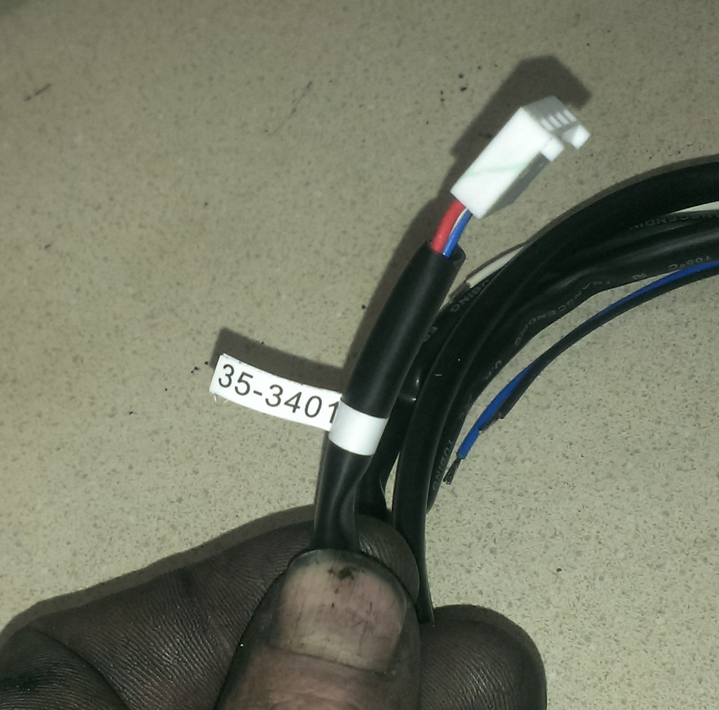
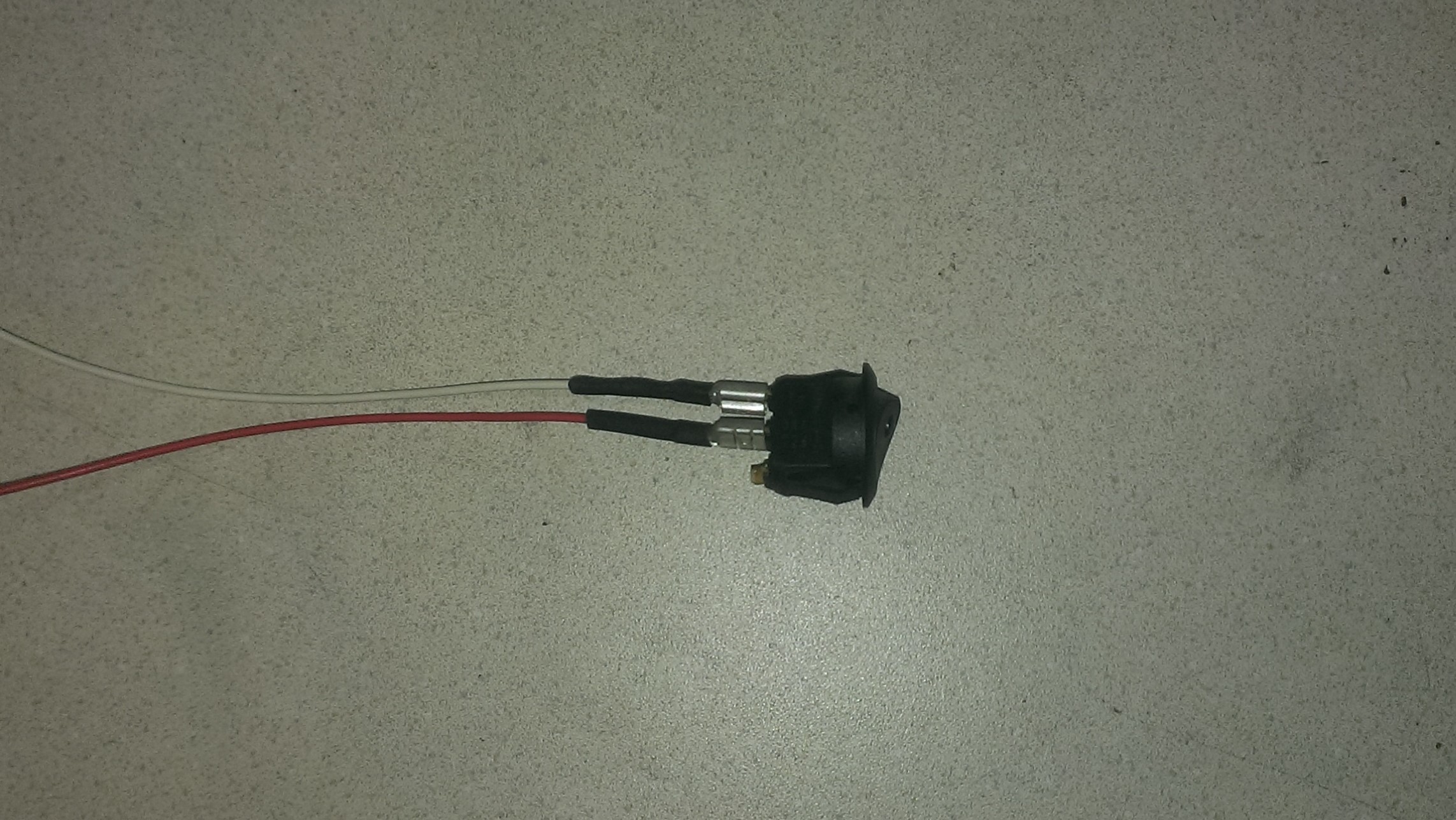
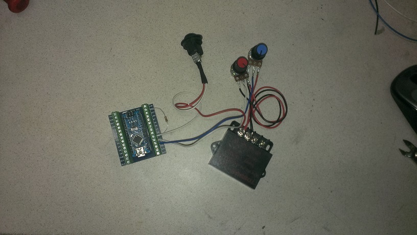
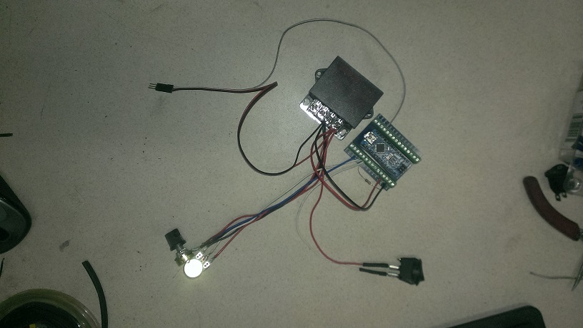
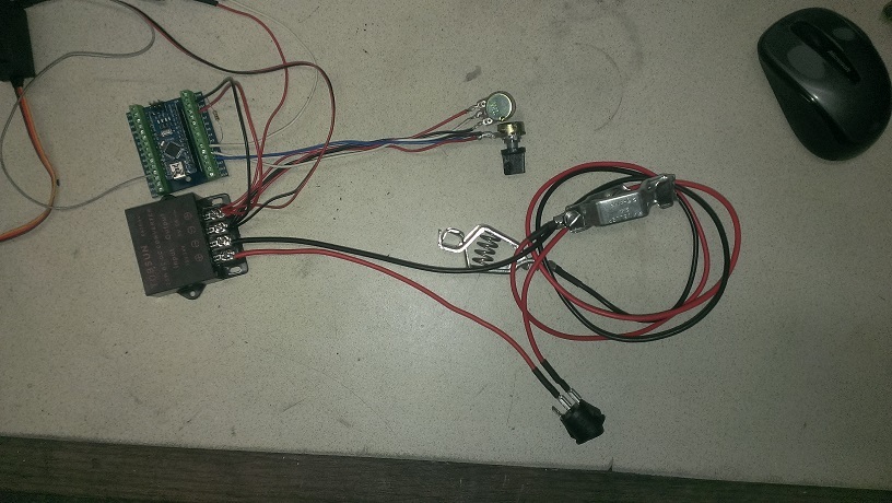
I made a change to this code as well. This code uses a momentary switche instead of an on / off switch. There is a feed back pin (D2) that can be used to eluminate an LED to indicate that the code has switched into automix mode. I use the “Angle Eye” switches and wire this pin to the LED terminal on the switch. You then only have to press this button to switch modes. The LED is either on or off. On its in auto mode and off its in manual potentiometer adjust mode.

#include <Servo.h> 
Servo AFR_Servo;  // create servo object to control a servo 


//VG 02 Wide Band Mixture Controller V1.3
//Craeted by Matt Ryder, Vulcan Gasifier LLC / Thrive Energy Systems May 5, 2015
//website; https://www.thriveoffgrid.net/
 //Prior edit; June 22, 2015 
 //Change log
 //April 30,2017 - Todd Harpster
 // added contraint to calculated delays after mapping to keep them in range
// read the O2 sensor just once per loop
// add table of expected delays based upon O2 sensor value
 //April 30, 2017 - Todd Harpster
 // v2 control loop
 // refactored code to use mode variable and switch statement to 

 // This code requires an AEM O2 sensor kit with LSU 4.9 sensor Part # 30-4110

// These constants won't change:
const int O2SensePin = A4;    // pin that the O2 sensor is attached to
const int ModePin = A2;   //Pin Auto Mode Switch is attached to
const int AFR_ManPin = A3; // Reads the O2 Manual Adjust Potentiometer on pin A1
const int ModeLED = 02; // Output pin to uliminate Mode button LED Status

// constants for our mode values
const int Mode_Override = 1;
const int Mode_Rich = 2;
const int Mode_Stoichiometric = 3;
const int Mode_Lean = 4;


//tunable parameters below
const int RichCon1 = 600; // Threshold limit for Rich gas condition
const int LeanCon1 = 750; //Threshold limit for lean gas condition
//Note make sure O2 Sensor Adapter Tube is long enough and creates sufficiant back presure
const int MinTuningServoPosition = 40;  // never fully close the valve in O2 loop mode
const int MaxTuningServoPosition = 140; // wide open

int mode = 0;              // loop operating mode
int pos = 0;              // variable to store the servo position
int val;                  // variable to read the value from the analog pin 
int lastpos = val;        // variable to store the servo last position
int ModeStatus = 0;    // variable for reading the Fuel Mixer Mode status

void setup() 
{ 
  //analogReference(INTERNAL);
  AFR_Servo.attach(06);     // attaches the servo on pin 9 to the servo object 
  pinMode(ModeLED, OUTPUT);  //ModeLED Status assinged as ouput pin

  Serial.begin(9600);
    
  // Need to create a set point for servo start position after manual tuning
  {
    val = analogRead(AFR_ManPin);  // reads the value of the potentiometer (value between 0 and 1023) 
    val = map(val, 0, 1023, 40, 140);     // scale it to use it with the servo (value between 0 and 180) 
    AFR_Servo.write(val);                  // sets the servo position according to the scaled value 
    lastpos = val;                       // sets lastpos to equal the position of the manually set position
    delay(10);                           // waits for the servo to get there 
 }
} 

// 
// O2 Sensor Reading    Delay
// =================    ====================
// Manual               10
// Rich     0 - 700     variable 500 - 800
// Stoichi  701-899     500
// Lean  750 - 1023     variable 800 - 450           
// 

void loop() 
{
  // read the state of the pushbutton value:
  //ModeStatus = digitalRead(ModePin);
  // read the value of the O2 sensor:
 //Todd - read the O2 sensor once for this loop and store in sensorReading
  int sensorReading = analogRead(O2SensePin);
  int ModePin = digitalRead(A2);

  //variable to hold mode for this time through the loop
 int mode = Mode_Stoichiometric;    // assume O2 reading is not too rich or not too lean, just right
  int delayms = 500;            // 500 ms delay as a default value - it case it doesn't get changed below

 if (ModePin == HIGH) {
    ModeStatus = ModeStatus +1;
    Serial.println(ModeStatus);
    delay(100);
 } else { 
    if ( ModeStatus >= 2) {
       ModeStatus = 0;
       Serial.println(ModeStatus);    
       delay(100);    
    }     
   }

  if (ModeStatus == 0) {
    mode = Mode_Override;
    digitalWrite(ModeLED, LOW);
  } else {      
    if ( sensorReading <= RichCon1 ) {
      mode = Mode_Rich;
      digitalWrite(ModeLED, HIGH);
    }
    if (sensorReading >= LeanCon1 ) {
       mode = Mode_Lean;
       digitalWrite(ModeLED, HIGH);     

    }
  }

  switch (mode) {
    case Mode_Override:
      val = analogRead(AFR_ManPin);           // reads the value of the potentiometer (value between 0 and 1023)
      val = map(val, 0, 1023, 45, 135);      // scale it to use it with the servo (value between 0 and 180) 
  AFR_Servo.write(val);                   // sets the servo position according to the scaled value 
  lastpos = val;                        // sets lastpos to equal the position of the manually set position
  delayms = 10;                          // waits for the servo to get there 
  break;
  
  case Mode_Rich:
  // move the air mixture servo to lean out by adding air
  lastpos = constrain(lastpos+1, MinTuningServoPosition, MaxTuningServoPosition);  // add 1 but make 
  //sure it stays in range
  AFR_Servo.write (lastpos);                          // tell the servo where to go
  val = map(sensorReading, 0, RichCon1, 50, 300);  // Richer mixtures get shorter delay
  val = constrain( val, 50, 300);                  // Keep values between 100 and 400 ms
  delayms = val + 300;                              // increase delay so minimum is 500 ms - max is 800 ms
  break;
  
case Mode_Stoichiometric:
  delayms = 2000;                                    // no need to move servo set delay to check back in 500 ms
  break;
  
case Mode_Lean:    
  // move the air mixture servo to decrease air to make richer
  lastpos = constrain(lastpos-1, MinTuningServoPosition, MaxTuningServoPosition);  // subtract 1 but make sure it stays in range
  AFR_Servo.write (lastpos);                            // tell the servo where to go
  val = map(sensorReading, 1023, LeanCon1, 650, 800); // the leaner the mixture the shorter the delay - need to adjust quickly
  val = constrain(val, 450, 800);                     // keep the delay between 450 and 800 ms
  delayms = val + 500;
  break;
  
otherwise:
  //this shouldn't happen
  break;
}

//wait for a little bit before doing this again
delay(constrain(delayms,250,1250));                 // use contrain to be completely sure delay value is reasonable
}
5 Likes