Ok here is the latest code update 5/26/23
The last update had some issues I must have missed. When you paste the code in the IDE the formatting was messed up. If you find errors, all you have to do is set your curser at the front of text (the IDE highlights when it finds and error) and back space. These are parts coments that our supposed to be ignored getting sent to the next next line. When it does that the forward slashes are not there for the IDE to ignore that text. So the IDE is seeing this text that is not actual code and it will return an error.
It will look something like this.
intconstant = 0; // this is example of the code
not pasting over to the IDE correctly.
Here is this corrected
intconstant = 0; // this is example of the code not pasting over to the IDE correctly.
Note how I had to bring the lower line of text back up to the line before.
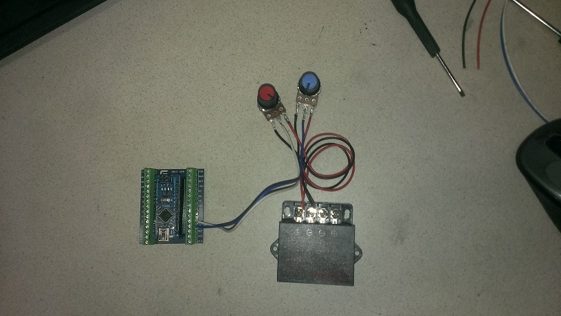
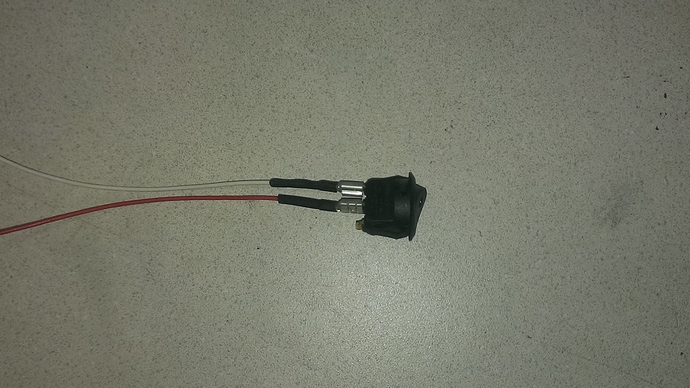
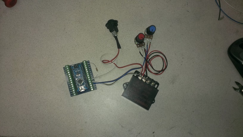
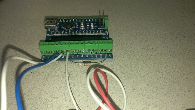
I made a change to this code as well. This code uses a momentary switche instead of an on / off switch. There is a feed back pin (D2) that can be used to eluminate an LED to indicate that the code has switched into automix mode. I use the “Angle Eye” switches and wire this pin to the LED terminal on the switch. You then only have to press this button to switch modes. The LED is either on or off. On its in auto mode and off its in manual potentiometer adjust mode.
#include <Servo.h>
Servo AFR_Servo;  // create servo object to control a servo


//VG 02 Wide Band Mixture Controller V1.3
//Craeted by Matt Ryder, Vulcan Gasifier LLC / Thrive Energy Systems May 5, 2015
//website; https://www.thriveoffgrid.net/
 //Prior edit; June 22, 2015
 //Change log
 //April 30,2017 - Todd Harpster
 // added contraint to calculated delays after mapping to keep them in range
// read the O2 sensor just once per loop
// add table of expected delays based upon O2 sensor value
 //April 30, 2017 - Todd Harpster
 // v2 control loop
 // refactored code to use mode variable and switch statement to

 // This code requires an AEM O2 sensor kit with LSU 4.9 sensor Part # 30-4110

// These constants won't change:
const int O2SensePin = A4;    // pin that the O2 sensor is attached to
const int ModePin = A2;   //Pin Auto Mode Switch is attached to
const int AFR_ManPin = A3; // Reads the O2 Manual Adjust Potentiometer on pin A1
const int ModeLED = 02; // Output pin to uliminate Mode button LED Status

// constants for our mode values
const int Mode_Override = 1;
const int Mode_Rich = 2;
const int Mode_Stoichiometric = 3;
const int Mode_Lean = 4;


//tunable parameters below
const int RichCon1 = 600; // Threshold limit for Rich gas condition
const int LeanCon1 = 750; //Threshold limit for lean gas condition
//Note make sure O2 Sensor Adapter Tube is long enough and creates sufficiant back presure
const int MinTuningServoPosition = 40;  // never fully close the valve in O2 loop mode
const int MaxTuningServoPosition = 140; // wide open

int mode = 0;              // loop operating mode
int pos = 0;              // variable to store the servo position
int val;                  // variable to read the value from the analog pin
int lastpos = val;        // variable to store the servo last position
int ModeStatus = 0;    // variable for reading the Fuel Mixer Mode status

void setup()
{
  //analogReference(INTERNAL);
  AFR_Servo.attach(06);     // attaches the servo on pin 9 to the servo object
  pinMode(ModeLED, OUTPUT);  //ModeLED Status assinged as ouput pin

  Serial.begin(9600);

  // Need to create a set point for servo start position after manual tuning
  {
    val = analogRead(AFR_ManPin);  // reads the value of the potentiometer (value between 0 and 1023)
    val = map(val, 0, 1023, 40, 140);     // scale it to use it with the servo (value between 0 and 180)
    AFR_Servo.write(val);                  // sets the servo position according to the scaled value
    lastpos = val;                       // sets lastpos to equal the position of the manually set position
    delay(10);                           // waits for the servo to get there
 }
}

//
// O2 Sensor Reading    Delay
// =================    ====================
// Manual               10
// Rich     0 - 700     variable 500 - 800
// Stoichi  701-899     500
// Lean  750 - 1023     variable 800 - 450
//

void loop()
{
  // read the state of the pushbutton value:
  //ModeStatus = digitalRead(ModePin);
  // read the value of the O2 sensor:
 //Todd - read the O2 sensor once for this loop and store in sensorReading
  int sensorReading = analogRead(O2SensePin);
  int ModePin = digitalRead(A2);

  //variable to hold mode for this time through the loop
 int mode = Mode_Stoichiometric;    // assume O2 reading is not too rich or not too lean, just right
  int delayms = 500;            // 500 ms delay as a default value - it case it doesn't get changed below

 if (ModePin == HIGH) {
    ModeStatus = ModeStatus +1;
    Serial.println(ModeStatus);
    delay(100);
 } else {
    if ( ModeStatus >= 2) {
       ModeStatus = 0;
       Serial.println(ModeStatus);
       delay(100);
    }
   }

  if (ModeStatus == 0) {
    mode = Mode_Override;
    digitalWrite(ModeLED, LOW);
  } else {
    if ( sensorReading <= RichCon1 ) {
      mode = Mode_Rich;
      digitalWrite(ModeLED, HIGH);
    }
    if (sensorReading >= LeanCon1 ) {
       mode = Mode_Lean;
       digitalWrite(ModeLED, HIGH);

    }
  }

  switch (mode) {
    case Mode_Override:
      val = analogRead(AFR_ManPin);           // reads the value of the potentiometer (value between 0 and 1023)
      val = map(val, 0, 1023, 45, 135);      // scale it to use it with the servo (value between 0 and 180)
  AFR_Servo.write(val);                   // sets the servo position according to the scaled value
  lastpos = val;                        // sets lastpos to equal the position of the manually set position
  delayms = 10;                          // waits for the servo to get there
  break;

  case Mode_Rich:
  // move the air mixture servo to lean out by adding air
  lastpos = constrain(lastpos+1, MinTuningServoPosition, MaxTuningServoPosition);  // add 1 but make
  //sure it stays in range
  AFR_Servo.write (lastpos);                          // tell the servo where to go
  val = map(sensorReading, 0, RichCon1, 50, 300);  // Richer mixtures get shorter delay
  val = constrain( val, 50, 300);                  // Keep values between 100 and 400 ms
  delayms = val + 300;                              // increase delay so minimum is 500 ms - max is 800 ms
  break;

case Mode_Stoichiometric:
  delayms = 2000;                                    // no need to move servo set delay to check back in 500 ms
  break;

case Mode_Lean:
  // move the air mixture servo to decrease air to make richer
  lastpos = constrain(lastpos-1, MinTuningServoPosition, MaxTuningServoPosition);  // subtract 1 but make sure it stays in range
  AFR_Servo.write (lastpos);                            // tell the servo where to go
  val = map(sensorReading, 1023, LeanCon1, 650, 800); // the leaner the mixture the shorter the delay - need to adjust quickly
  val = constrain(val, 450, 800);                     // keep the delay between 450 and 800 ms
  delayms = val + 500;
  break;

otherwise:
  //this shouldn't happen
  break;
}

//wait for a little bit before doing this again
delay(constrain(delayms,250,1250));                 // use contrain to be completely sure delay value is reasonable
}
