Friends, I present to you my version of the gas generator system for a wood-fired car. this is my outdated design, it served me for almost 2.5 years and I drove 22 thousand kilometers on it. The main reason for sending it to the scrap is the emergence of new knowledge and ideas that I wanted to implement in hardware and create a more perfect version 10.0. But back to version 9.0. The maximum speed for a car with a 9.0 gas generator was 120 km / h, firewood consumption was approximately 15-17 kg / 100 km. A gas generator was made of stainless steel 0.5 mm thick, which made it possible to achieve the weight of the entire system no more than 30 kg in the equipped form. The main mistake in its creation was the use of conventional wire for welding, which affected the survivability of the welds in the hopper area.
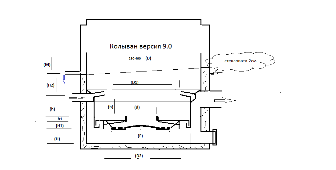
This is a schematic drawing of the 9.0 system, which shows the changes that have been made relative to my version with the 8.0![]() logo. The first is the raised tuyeres (approximately 20 degrees). Second, there is a change in the number of tuyeres - there are seven of them with a diameter of 8.2 mm. Third, this is a change in the bottom of the gasification chamber, namely, a removable bottom with a neck. The very bottom of the chamber and the neck are made with thermal gaps and are not rigidly fixed. Also added a heat shield and a movable grate. There is also a screen for keeping coals on the grate, which reduces the removal of large fractions from the core.
logo. The first is the raised tuyeres (approximately 20 degrees). Second, there is a change in the number of tuyeres - there are seven of them with a diameter of 8.2 mm. Third, this is a change in the bottom of the gasification chamber, namely, a removable bottom with a neck. The very bottom of the chamber and the neck are made with thermal gaps and are not rigidly fixed. Also added a heat shield and a movable grate. There is also a screen for keeping coals on the grate, which reduces the removal of large fractions from the core.
The version 9.0 system forced me to think about the gas purification system, since the sawdust did not suit me at that time. Therefore, version 9.0 has become a testing ground for new generations of gas filters.
Hello Yevgen, all praise for creativity, thank you very much for sharing your knowledge with us
Hello Joni,
Have you yet tried sheep’s wool for a filtering media?
Thank you
Steve Unruh
Wet winter wind storm here. Grid power has been out. I must type fast before the next interruption. Our new satellite Internet would require a second running generator.
Ha! Ha! New systems always show something then to system improve, yes. S.U.
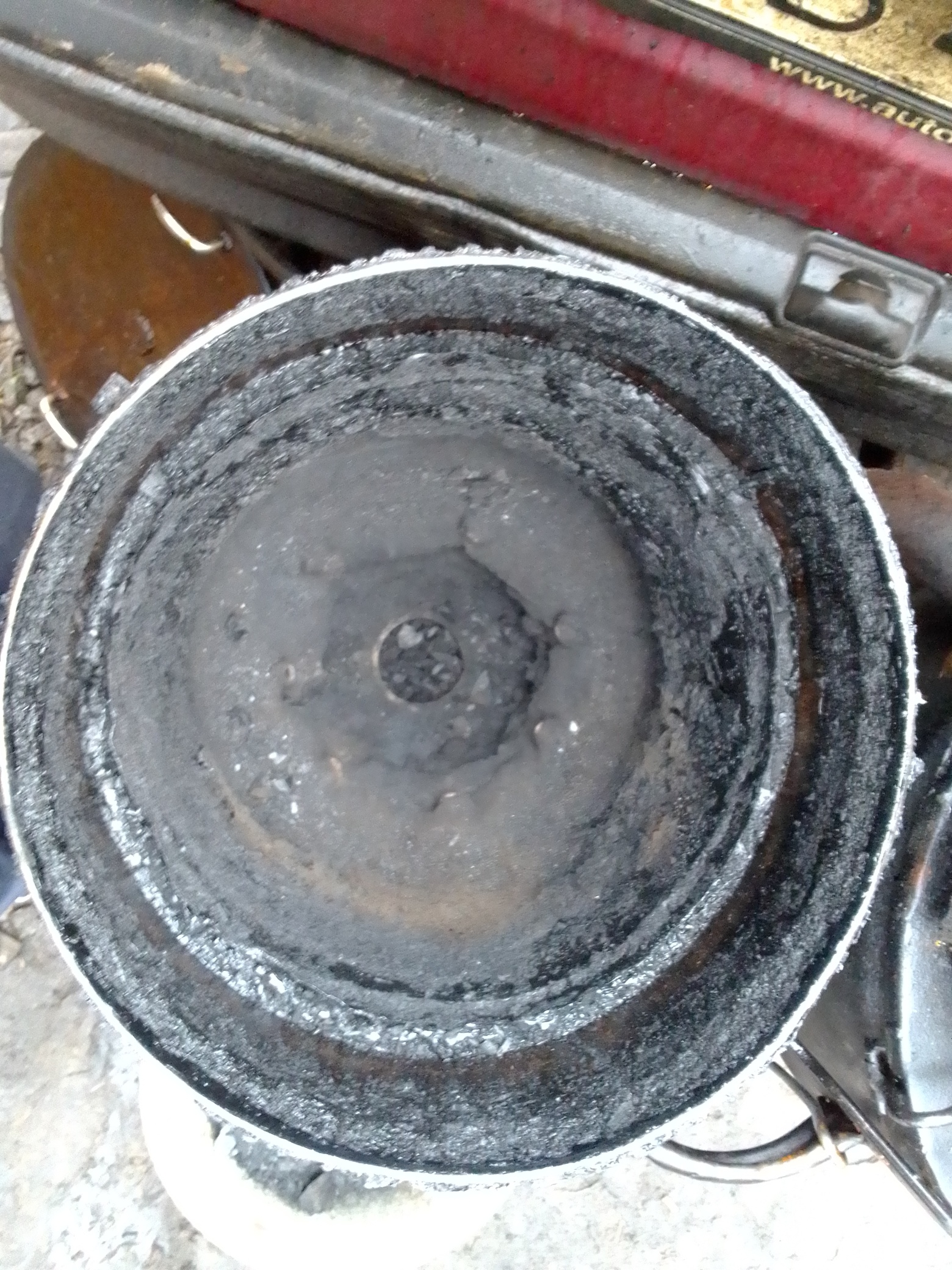
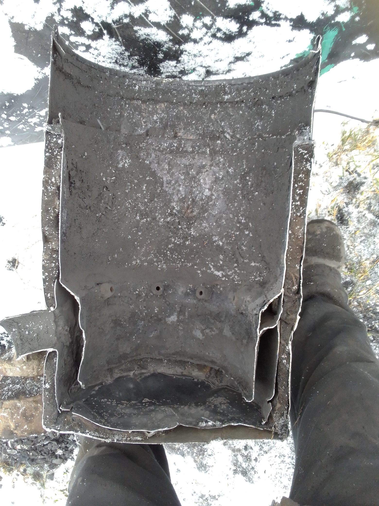
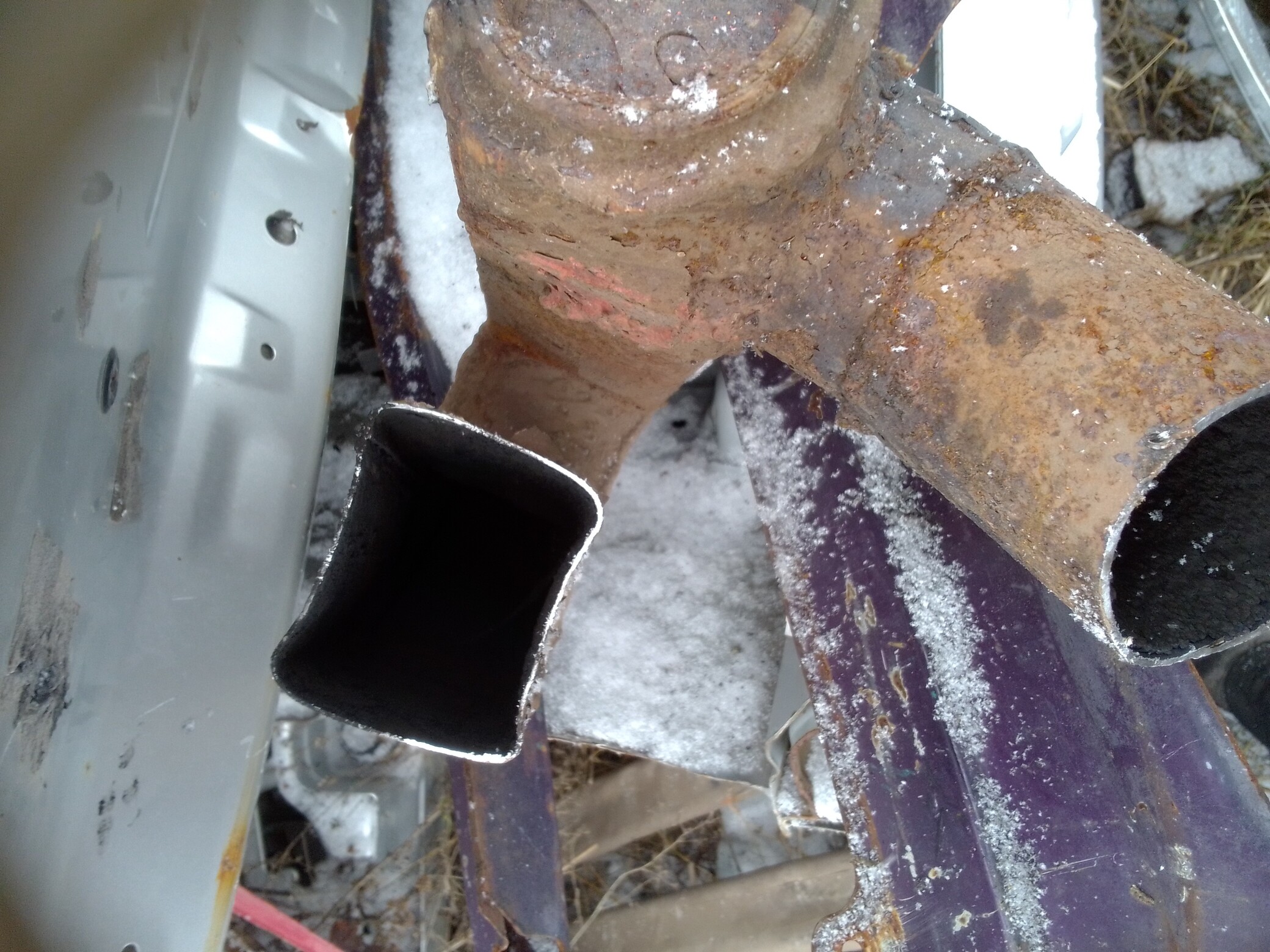
Especially for your forum today, I made a longitudinal section of version 9.0 to show it is intact. As you can see, the metal with a thickness of 05 mm was not damaged anywhere, and the system itself was operational until the last moment.
I made the cooler from an old car, it has a thickness of 08mm and is galvanized on both sides. Its total surface area is almost 2 square meters, so the filter remains cold even in summer.
Hello Steve,
the first test material after sawdust was a bag-shaped fabric filter in front of which small cubes of broken glass were placed on a grid (glass of old cars, they tend to break into cubes). These glass cubes created a layer of 10 cm and then a fabric filter with an area of 1 square meter (I used old jeans from which my wife Natalya sewed a bag for me). The main disadvantage of this type of filter was that when the fabric got wet, it passed gas very poorly and showed great resistance, and the broken glass had a huge weight. The next option was to replace the glass with large sawdust, they dried the gas better and the filter resisted much less.
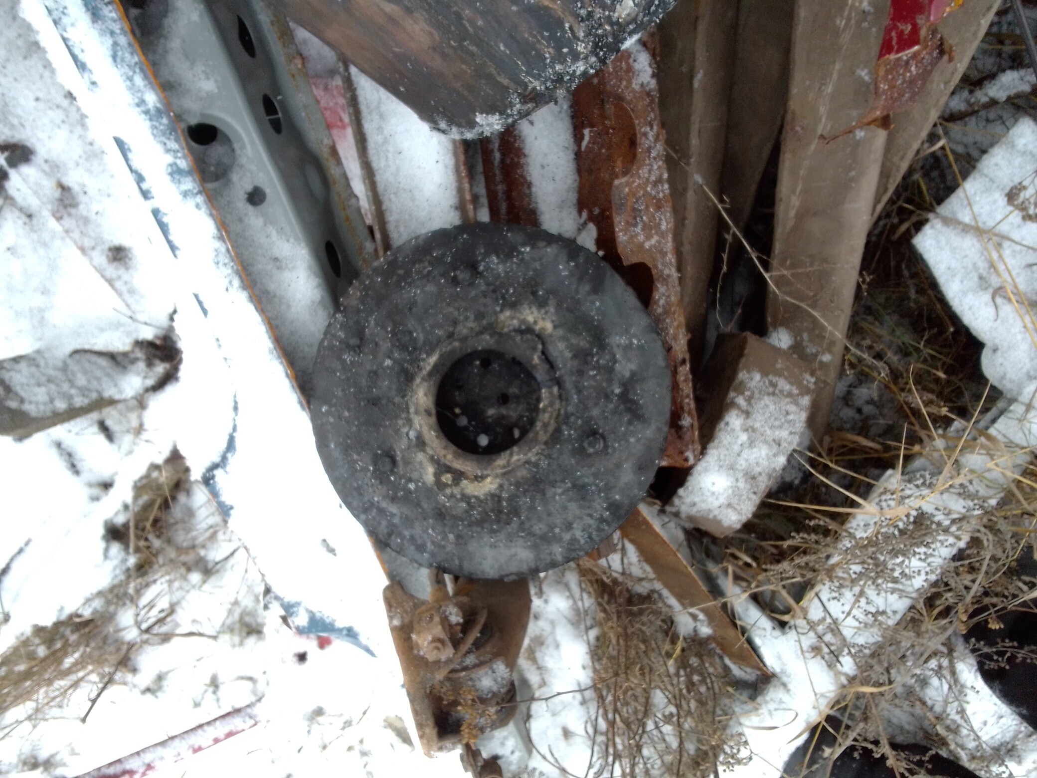
The only damaged part of the gas generator was the filter housing; an iron barrel from under the oil with a capacity of 60 liters was adapted for it. The formic acid contained in the condensate did its job and left a lot of holes …

Hi Joni, great cross section of your old gasifer. You have just done a first time ever on DOW with this picture as far as I know. You can see where the hot gases exited the gasifer, the fire tube really got hot on the wall. Looking at your tuyeres they look like they are in very good shape. Thank you for all of the pictures of your obsolete scrap out unit.
Bob
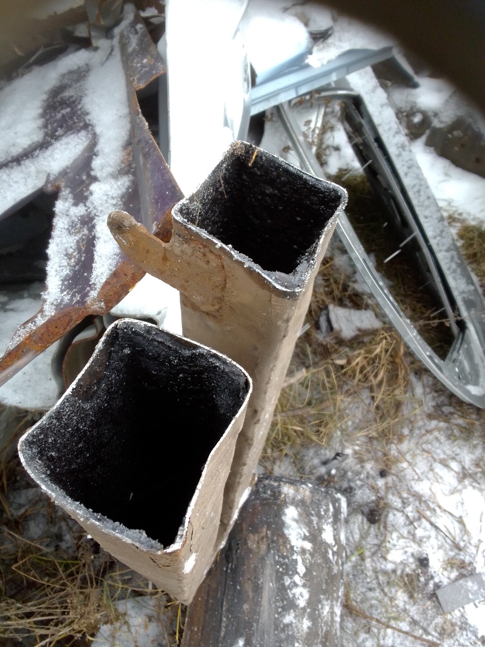
Hi Joni, I noticed in your drawing diagram and looking down into your gasifer that the hopper and fire tube is off set in the gasifer barrel. This would make welding the tar gutter in place more difficult. What was the reasoning for this when you built the gasifer unit.
Bob
Hi Bob,
I am engaged in car restoration after an accident (this is how I earn my living) and welding three pieces of iron together is not a problem for me, but based on the difficulties associated with the manufacture of collapsible flanges, their cost and the impact of their presence on the weight of the system, I give priority welding. If all operations and the sequence of their execution are well thought out, then assembling the system is not worth a lot of effort.
Hello Joni,
If I may ask . . . . where have you found it best to locate internally your engine exhaust vapor draw tube?
In the condensate gutter?
All of the upper edge area has the typical black-goo build up. So the outer wall would be unusable.
Yes your ash floor show the need for the heat shielding on the under side of your restriction plate. To protect from grate held char glow.
You cannot use vertical distance to protect.
Thank You
Steve Unruh
Steve,
I think yes, the condensation chute is a good place.
Hi Joni that gives me a very clear cut look of what at least 1 half of your gasifier looks like thank you, very smart indeed 
Dave
Dear Joni,
thanks for sharing your ideas and the cross cut!
Looking at your 8.0 and 9.0 version I wonder that your reduction zone between restriction ring and grate is very small. Especially the measure of H1 is very low (20 - 30 mm on version 8.0)
In older books it seems like oxidation and reduction zone are same size (book from Sweden, around 1970)
Kristijan and Jan have tried the other way round: No grate and big reduction zone.
Well, your system works fine for you and theirs for them. But have you ever tried a larger reduction zone? What are your thoughts about the size of the reduction zone?
One question about your filter: You use 10 cm sawdust and then fabric filter of old jeans? And no soot in the engine?
How often do you need to clean or replace the sawdust and fabric filter?
Thank you for your thoughts.
Til
Thank you for your post, love seeing how people put their systems together
Тіl,
as you can see, this is not my first system, yes, I also started with a long recovery zone, but came almost to its absence … There are also many disagreements in the books of the USSR on this topic, whether the zone is needed or not … On my own bitter experience, I made a simple conclusion for myself - needed, but very small. You ask - what about the resin, but I will say that these are things that do not depend on each other. As for the filter, I also wanted to talk, since it was not the last option, but only a trial one. There was no soot in the engine, but there were many other drawbacks. As I said, the main drawback was the high resistance in wet form, and the second was that the fabric quickly collapsed due to the corrosive condensation environment … And later I tested a different design using a bubble filter.
Til, after trying it out for a couple years I’ve come to the conclusion it’s not needed most of the time. The bottom char gets hot enough to be of any use only when running really hard for a long period of time. The char is too spred out to keep the heat in and to be helpful for short power bursts.
Also, it collects ash at shutdown. It takes me up to 20 minutes of driving before it clears up and all the char is clean enough to give me full power. I’ve probably replaced most of it by then and maybe even reached my destination ![]()